Inspection robot
(→Operation) |
(→Firmware) |
||
| Line 76: | Line 76: | ||
===Firmware=== | ===Firmware=== | ||
| − | ===== | + | =====Bugs===== |
An earlier version of the firmware contains a bug that causes the firmware to crash if the PWM duty cycle becomes larger than 76% (196/255). When the firmware crashes, communication and control are lost and the servomotor will spin out of control. It is highly recommended to test if a servomotor has this bug, before use. This is tested by removing a gear from the gear-train of the servomotor and then demand a large PWM duty cycle (a P-gain of 150 and error of about 500 achieves this). If the error is present, update the servo firmware to the August 2015 version (version can be seen in main.c). | An earlier version of the firmware contains a bug that causes the firmware to crash if the PWM duty cycle becomes larger than 76% (196/255). When the firmware crashes, communication and control are lost and the servomotor will spin out of control. It is highly recommended to test if a servomotor has this bug, before use. This is tested by removing a gear from the gear-train of the servomotor and then demand a large PWM duty cycle (a P-gain of 150 and error of about 500 achieves this). If the error is present, update the servo firmware to the August 2015 version (version can be seen in main.c). | ||
| + | |||
| + | Another bug in the servo firmware, is the inclusion of register 0x2F in the register range that is saved to the onboard EEPROM. Because register 0x2F is used as a communication timeout register, the value of this register changes very frequently. This implicates that in the time between a checksum has been created and register values are written to EEPROM, the value of this register has most likely changed. Thus, when restoring register values from EEPROM, the checksum will rarely match the stored data resulting in default register values being loaded. This causes the servomotor's I<sup>2</sup>C address to be reset to the default value of ''10'' (0xA). | ||
=====Features===== | =====Features===== | ||
As of August 2015, the servomotor firmware for the modified OpenServo PCB supports the following: | As of August 2015, the servomotor firmware for the modified OpenServo PCB supports the following: | ||
| − | |||
| − | |||
*Sampling of Back-EMF (only up to duty-cycle of 76%, due to discharge time of armature coil). | *Sampling of Back-EMF (only up to duty-cycle of 76%, due to discharge time of armature coil). | ||
Revision as of 10:07, 7 August 2015
Installation and use noted for 4/6-legged inspection robot.
Contents |
Mobotware on a Raspberry PI
Installation - see How-to guide on main page.
Mobotware on a Beaglebone Black
Installation - ask Søren Hansen in 326/014 or Jens Christian Andersen in 326/008.
A small guide has been made, describing how to connect to the Beaglebone Black, how to mount it's file system, change I2C frequency and how to run RHD and RHDtest. The guide can be downloaded here: BBB_guide_101v3.pdf
RHD Plugin
Starting
When Mobotware has been installed, log on to the Beaglebone Black using a terminal with the following command:
ssh root@<BBB-ip>
Then navigate to the appropriate plugin folder. The exact path may vary depending on the installation. Most common paths are:
rhd/plugins/6legged/
rhd/trunk/plugins/6legged/
This folder contains the configuration file rhdconfig.xml which is used for configuring the plugin parameters such as sampling period, declaration of servomotors and their parameters. Then, from the folder containing rhdconfig.xml, the RHD is started and will load the plugin which will initiate I2C communication with the servo motor. To read out/set variables, RHDtest can be started in another terminal window.
NOTE: The RHD plugin needs to be compiled before using it for the first time after installation of Mobotware. This is done by navigating to the appropriate folder above, and writing the command "Make".
Features
The plugin is configured by modifying the XML-file: rhdconfig.xml.
- Setting of PID gains from rhdconfig.xml
- Changing of servo I2C address
- Keeps working if connection to one or more servomotors are lost
- Supports up to 24 servomotors
- Debug mode
Servomotor
Hardware
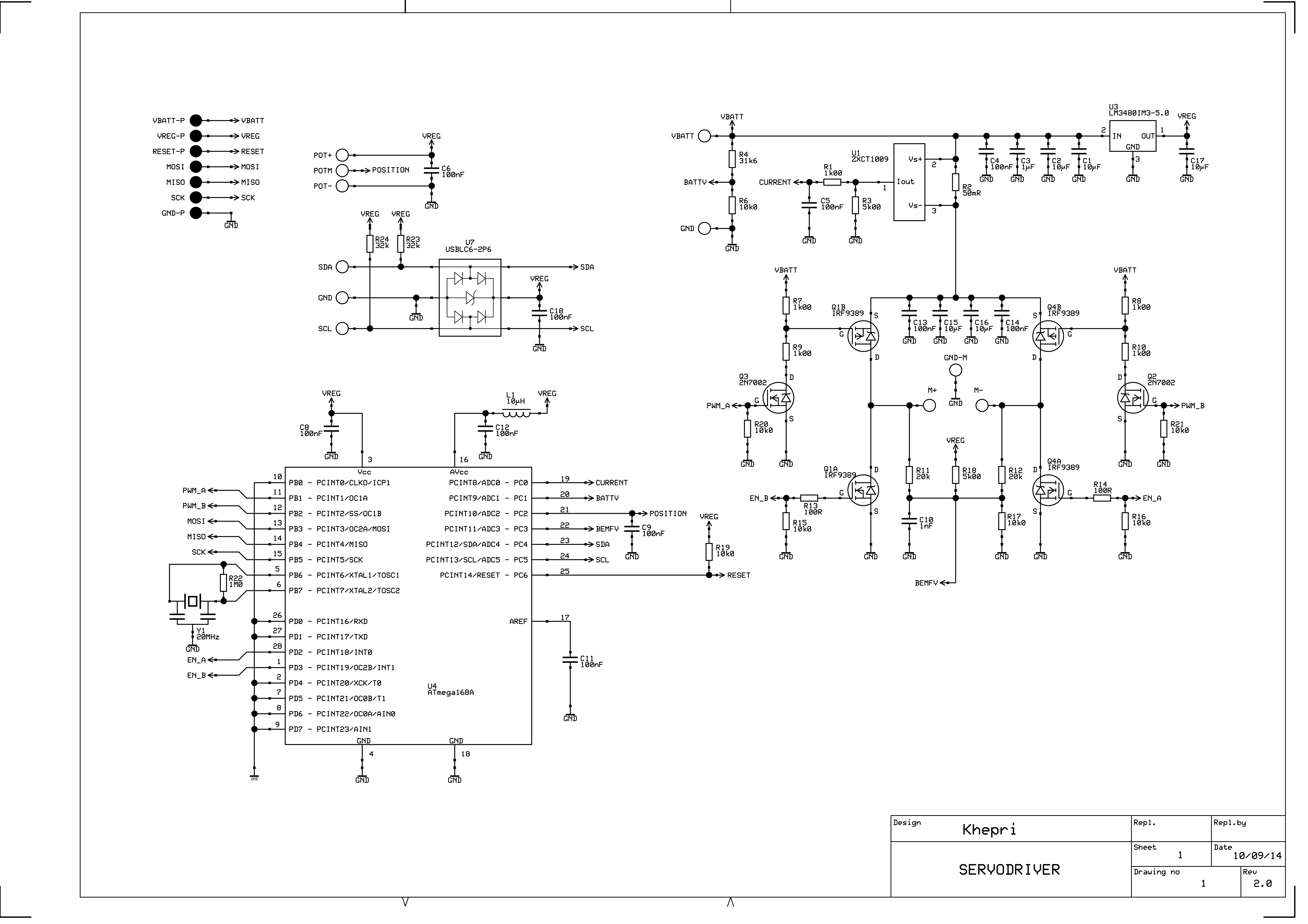
The Hitec HS646-WP electric servo motor are used for the inspection robot. See Hitec's website for specifications. The servo does not provide feedback by default, and is therefore augmented with the OpenServo project's PCB and software/firmware. The PCB and firmware are modified to fit the purpose of the inspection robot, and utilizes an ATmega168 MCU (datasheet, 34 MB PDF).
Potentiometer
Mounting: Green towards motor, yellow in center and red away from motor, or maybe more likely, motor is turned 180 deg. NOTE: The A/D converter of the ATmega168 MCU is 10-bits, giving potentiometer readouts between 0-1023.
If the potentiometer or motor terminals have been inverted, this can be compensated for by changing the macro SWAP_PWM_DIRECTION_ENABLED in the firmware source file config.h. This should only be a problem if new servomotors are augmented with the OpenServo PCB and the installer are not cautious.
Power
The supply voltage should be at least 6.5V to allow the regulator to properly produce 5V for the MCU. The maximum supported voltage is around 18V (the maximum rating of the weakest components). Operating with 10-12V is considered sufficient.
PCB Layout
The layout of the modified OpenServo PCB with connections can be seen in the pictures below (front and backside). A diagram/schematic of the modified OpenServo PCB can be seen here
The modification to the standard OpenServo PCB consists of moving two capacitors to make room for the motor (visible on side A).
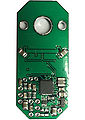
Modified OpenServo PCB, side A
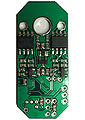
Modified OpenServo PCB, side B
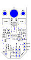
Diagram of Modified OpenServo PCB, side B


Firmware
Bugs
An earlier version of the firmware contains a bug that causes the firmware to crash if the PWM duty cycle becomes larger than 76% (196/255). When the firmware crashes, communication and control are lost and the servomotor will spin out of control. It is highly recommended to test if a servomotor has this bug, before use. This is tested by removing a gear from the gear-train of the servomotor and then demand a large PWM duty cycle (a P-gain of 150 and error of about 500 achieves this). If the error is present, update the servo firmware to the August 2015 version (version can be seen in main.c).
Another bug in the servo firmware, is the inclusion of register 0x2F in the register range that is saved to the onboard EEPROM. Because register 0x2F is used as a communication timeout register, the value of this register changes very frequently. This implicates that in the time between a checksum has been created and register values are written to EEPROM, the value of this register has most likely changed. Thus, when restoring register values from EEPROM, the checksum will rarely match the stored data resulting in default register values being loaded. This causes the servomotor's I2C address to be reset to the default value of 10 (0xA).
Features
As of August 2015, the servomotor firmware for the modified OpenServo PCB supports the following:
- Sampling of Back-EMF (only up to duty-cycle of 76%, due to discharge time of armature coil).
- Sampling of voltage, position and armature current.
- PID control (The integration is untested).
- 500 Hz PWM control.
- 500 Hz internal sampling rate (once per PWM cycle).
- Up to 400 kHz I2C bus frequency (Max supported by the ATmega168 MCU).
Needs Testing
- Integration part of build-in PID-controller.
- Anti-windup limits of integrator.
Programming of Servomotors
In order to update the firmware of the servomotors, the backside is opened by unscrewing the four philips-head screws and removing the back panel. The OpenServo PCB should be visible with side B facing out. The servomotor is then CAREFULLY placed in the created programming stand. There is only one way to orient the servomotor correctly in the programming stand! When oriented correctly, the pins of the programmer will connect to terminals: MISO1, MOSI1, SCK1, RESET-P and GND-P of the modified OpenServo PCB (see diagram).
The servomotor is then programmed by connecting the programming stand to the ISP port of an STK500/600 programmer and using AVRdude.
NOTE: The servomotor needs external power while being programmed.

Operation
Worth Knowing
- A P-gain is needed to make the servo run. A value of about 50 is a good starting point.
- A D-gain does not affect the precision/overshooting. See the "Controller Characteristics" section for test results.
- Internal sampling of Back-EMF, voltage, position and current runs at 500 Hz (once per PWM cycle).
- Obtainable external sampling rates with 400 kHz I2C bus frequency is approx. 259-312 Hz with four servomotors (a single robot leg) and approx. 41-43 Hz with 24 servomotors (six legs of four servos).
Commands
By writing a command number to the scmd variable in RHDtest, the command is sent to the servomotor which performs special functions. The commands are listed in the table below.
| Cmd. No. | Action |
|---|---|
| 0x80 | Restart the microcontroller |
| 0x81 | Write simple checksum to read/write registers |
| 0x82 | Enable PWM to motor |
| 0x83 | Disable PWM to motor |
| 0x84 | Enable write of read/write protected registers |
| 0x85 | Disable write of read/write protected registers |
| 0x86 | Save read/write protected registers to EEPROM |
| 0x87 | Load read/write protected registers from EEPROM |
| 0x88 | Restore read/write protected registers from EEPROM |
| 0x89 | Change servo I2C address to saddr |
The registers saved to EEPROM are in the range 0x20 through 0x2E, which are the registers containing the I2C address, controller gains, PWM frequency divider and minimum/maximum position range of the servo (0-1023 is set by default)
Controller Characteristics
Tests have been conducted with regards to determining the precision of the servomotor depending on the PD-controller gains. The table below shows the results of different step responses. The servomotor is tested while standing on its own without any load. The steady-state position error ess, and error e (the step size), are in A/D units.
| P = 100, e = 600 | |||
|---|---|---|---|
| D = 0 | D = 50 | D = 100 | D = 150 |
| ess = 12 | ess = 15 | ess = 15 | ess = 15 |
From these results it is seen that the D-gain has a very limited impact on the controller performance.
In order to avoid overshooting too much, small steps have been performed with large P-gains. The idea is to obtain a precise movement for a large step by making multiple small ones. The results can be seen in the table below. The steady-state position error ess, and error e (the step size), are in A/D units (approximate).
| P = 400, D = 0 | |||||
|---|---|---|---|---|---|
| e = 25 | e = 50 | e = 75 | e = 100 | e = 200 | e = 500 |
| ess = 7 | ess = 2 | ess = 6 | ess = 5 | ess = 6 | ess = 9 |
| P = 400, D = 50 | |||||
|---|---|---|---|---|---|
| e = 25 | e = 50 | e = 75 | e = 100 | e = 200 | e = 500 |
| ess = 7 | ess = 2 | ess = 7 | ess = 8 | ess = 7 | ess = 8 |
| P = 400, D = 100 | |||||
|---|---|---|---|---|---|
| e = 25 | e = 50 | e = 75 | e = 100 | e = 200 | e = 500 |
| ess = 8 | ess = 1 | ess = 6 | ess = 3 | ess = 5 | ess = 9 |
These results are approximate as the steady state error varies a little between steps. From these results it can be seen that with a P-gain of 400 and a step-size of 50, good results are obtained (i.e. a small steady-state error). Again it is seen that the effect of the D-gain is negligible.
It is noticed that steady-state errors tend to be larger when stepping on the high end of the potentiometer (i.e. steps 750-775, 800-850, 700-900 etc.). It should also be noticed that steady-state errors tend to be larger when moving from a higher position to a lower one (i.e. a step from 900 to 700 yields a larger steady-state error than moving from 700 to 900).
Old RHD Plugin
The initial version of the RHD plugin was connected to a servomotor using the USBISS converter (USB-to-I2C), and is not longer used.
Setting and main status for N servos (up to 24) implemented. Debug status for 1 servo implemented (first 48 registers are monitored)
Commands (write with register adress above 0x7f) is working
0x82 (130) enable PWM
0x83 (131) disable PWM
etc - see main.c in software
Change of I2C address is not implemented in this version (There is a save to EEPROM command).