User interface
(→Mission) |
(→Mission) |
||
| Line 33: | Line 33: | ||
e.g.: | e.g.: | ||
| − | vel=-0.2, acc=3.0 : dist=1, time=12 | + | * vel=-0.2, acc=3.0 : dist=1, time=12 |
Drive backwards at a speed of 0.2m/s, accelerate with 3m/s2 for 1 meter (or max 12 seconds) | Drive backwards at a speed of 0.2m/s, accelerate with 3m/s2 for 1 meter (or max 12 seconds) | ||
Revision as of 18:37, 16 May 2016
Contents |
Screen dumps
The user interface can configure and run the robot, as well as inspecting almost all values on the robot. Written in python using Qt GUI library.
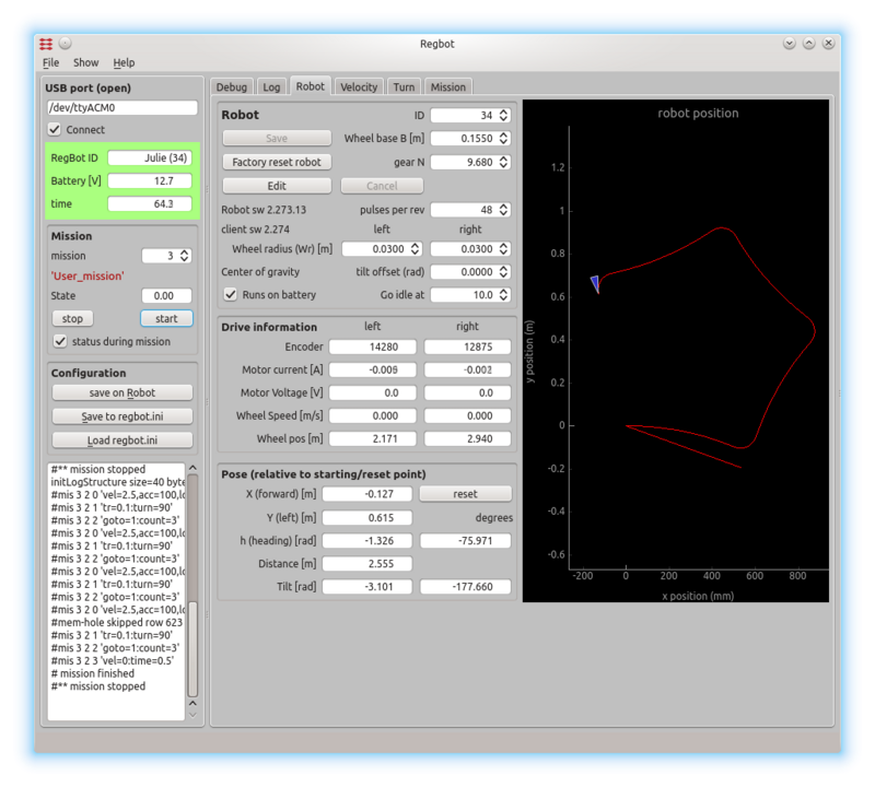
The interface looks like on figures below.
Figure 1. The general settings for the robot. The left panel is the general connection status and space for some messages from the robot. The central tab is mostly for configuration of the robot and some sensor and calculated values like pose and tilt. To the right is a fast graph of the last mission.
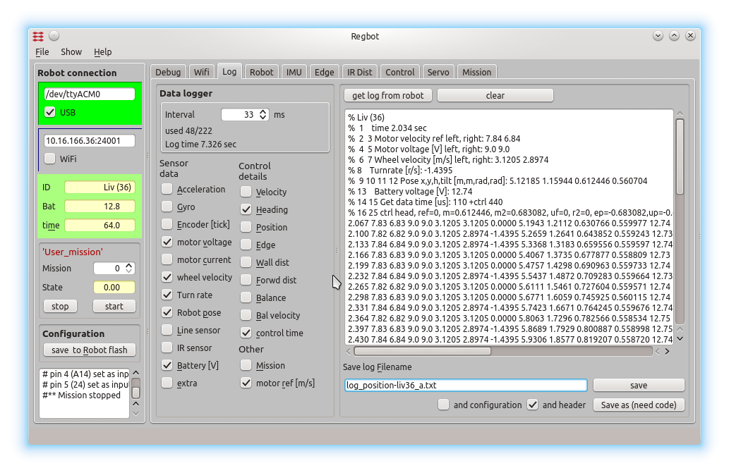
Figure 2. The data logging options. A number of sensor values and interface points in the robot software can be logged. The window text window shows loaded data from a mission. The log format is designed to be directly compatible with the 'load' function in MATLAB.
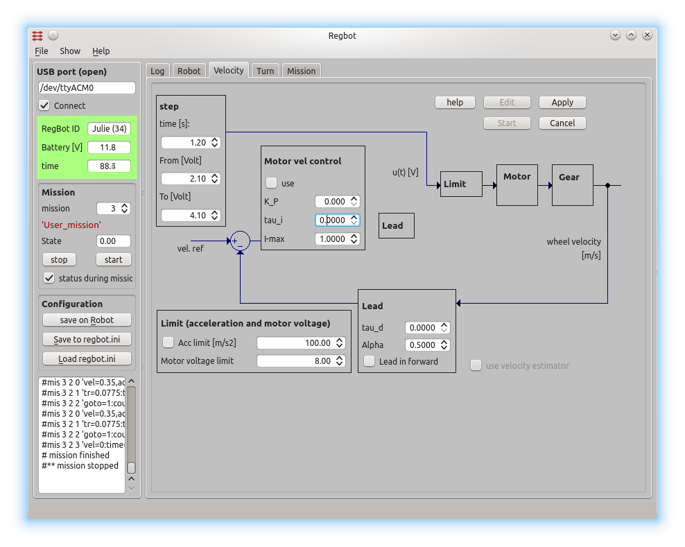
The GUI allows to make step responses for velocity and turn (and most of the other controllers). The step response is recorded in a buffer on the robot and is fetched in a MATLAB style file (as shown). Interface points that are recorded can be switched on and off to better utilize the limited buffer size on the robot (35kBytes).
Figure 3. This is a page to make a step response and insert controller values for velocity control. The same controller is used for both wheels.
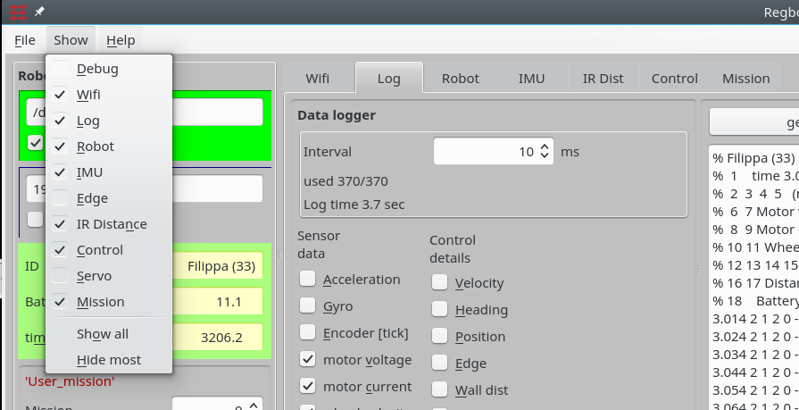
Figure 4. Other tab pages are available from the "show" menu.
Mission
Mission specification consist of mission lines, each line consist of two (lower case) parts divided by ':'
drive values : continue conditions (conditions are OR'ed)
e.g.:
- vel=-0.2, acc=3.0 : dist=1, time=12
Drive backwards at a speed of 0.2m/s, accelerate with 3m/s2 for 1 meter (or max 12 seconds)
Drive values
- VEL is velocity in m/s - positive is forward, 0=stop. uses last value if omitted.
- ACC is acceleration limit in m/s2. Uses last value if omitted.
- TR is turnradius in metre - positive, 0 is turn on the spot. straight if omitted
- LOG is log interval in milliseconds. Once started it continues until buffer is full.
- BAL is balancing, uses last value if omitted.
- LABEL is a label number that can be used by GOTO.
- GOTO is a jump to the label number given. This can be limited to COUNT use of goto, the count is then reset after the first skip. The goto can also be skipped if any other conditions are true when this line is reached. A line with a goto will never wait.
Line-sensor
If a line sensor is installed, then the following should work too:
- EDGER is following Right edge of line at -2..2 (in cm), positive is right
- EDGEL is following Left edge of line at -2..2 (in cm), positive is right
- WHITE set to 1 if follow-line tape is white, else 0
Distance sensor
If IR distance sensors are installed, then these should work:
- IRSENSOR is IR-sensor to use (1 is distance to a wall, and 2 is distance in front).
- IRDist is IR-distance to hold.
Threads
A command sequence may be divided into threads. The default thread has number 1.
- THREAD=3 means that this and all following lines are handled by one thread (with number 3). All threads are activated at time 0.
Example
thread=2
   edgel=0.0, white=1, log=20.0: time=4.5
   : time=3.5
thread=8
   vel=0.4: time=1.0
   vel=0.2: time=1.0
   vel=0.0: time=1.0
   vel=0.3: time=1.0
thread=9
   bal=1: time=3.5
   bal=0
Here the first thread controls drive method, first 3.5 seconds follow a line edge, then go straight for 3.5 seconds. The second thread (with number 8) controls the velocity over the first 4 seconds. The last thread (with number 9) controls when to use balance.
The mission is finished when all threads has ended.
Two threads may controls the same setting (the last one is in effect), however this should not be attempted with drive mode (i.e. follow edge or follow wall or turn, this can give unpredicted results).
The thread number is pt. not used to determine the execution order of the threads (uses script order).
Events
Events can be generated if an event=X command is entered in the drive value side of the colon. The event is activated when the line is activated. More than one event can be activated in the same line, e.g.:
- vel=0.2,event=7,event=12:time=1
Here event 7 and 12 are activated at the same time as the velocity is set to 0.2.
Continue conditions
':' is separation of parameters and continue condition.
- DIST is driven distance in this mission line - positive meters
- TURN is angle turned in this mission line - degrees, positive is Left (CCW if forward speed)
- TIME is max time in this mission line - positive seconds
- COUNT is used with GOTO and GOTO will be ignored, if this line is executed more than this count
- XB,XW,LV is conditions relevant for the line sensor (if implemented) - see below
- IR1,IR2 is conditions relevant for IR distance sensors - se below
- TILT is tilt angle (especially useful if not in balance.
- EVENT is testing for events
- LOG is true when log is full (value is ignored but must be set)
The equal (=) sign can for some values (dist, turn, xb, xw and tilt) be replaced by '<' or '>', for most values (except xb and xw) an equal sign means equal or greater. NB! '>=', '==', '<=' and '!=' are not valid.
Example: Drive 0.2m then turn 30 deg to the right (turn radius=0, but will be more with acceleration being only 1m/s2) then drive another 1 second at a higher speed (or maximum 0.4m).
vel=0.2,acc=1 : dist=0.2
tr=0 : turn = -30
vel=0.5 : dist=0.4,time=1
Example Zig-zag sideways: drive 0.2m backwards and then turn 45 deg left, 45 deg right and a bit forward, repeated 2 times more with a goto (to label=6).
vel=-0.2, acc=2.0: dist=0.2
label=6:
tr=0.15: turn=45.0
tr=0.15: turn=-45.0
vel=0.2:dist=0.18
vel=-0.2,goto=6: count=2
Line sensor
This section is valid if a line sensor is installed and calibrated. Use "Edge" tab for calibration (put edge sensor "ON" and on a dark background and press "Calibrate no reflection" and then on a bright background and press "Calibrate white reflection", then "save on robot").
- XB, XW is test for crossing black/white line, value is 0..20, 0 is true on no crossing, 1..20 is confidence in crossing (20 is highest)
- LV is test for valid line 0=true for no valid line, 1=true for valid line. NB! A wooden (or dirty) floor is likely to give a valid line at times.
Example: Drive until a crossing black line is found or 2.5m is driven, then continue until the crossing line is gone (reached other side of line) and stop
vel=0.2, log=5, acc=2: xb>16, dist=2.5
:xb < 4,dist=0.2
vel=0:time=0.1
Example find white line and follow edge: Drive until (white) line is found - as before - then turn to the right and follow line for 0.5 m.
vel=0.2, log=5, acc=2: xw>16, dist=2.5
:xw < 4,dist=0.2
vel=0:time=0.3
tr=0,vel=0.2:turn=-90
edgel=0, white=1: dist=0.5
Distance sensor
IR1, IR2 is test for distance measured by IR sensor.
@todo Distance sensor is not tested much, and is therefore assumed not to work properly.
Tilt balance angle
TILT is test for tilt angle (0 is balance point)
Example:
@todo
Events
An event can be a test condition in a mission line, and can be generated by a mission line. Up to 32 events can be used, they are named "event=N", where N is a number in the range [0..31]. An event is valid for one sample period only (1ms).
Events can be created from the communication interface with the command like
<event=5>
An example could be like this (a not very functional example)
thread=2
  vel=0.2:time=1          # driving at speed 0.2 m/s for 1 second
  vel=0,event=7:event=5   # set speed to 0 and generate event 7, then wait for event 5
  vel=0.2:time=1          # speed back to 0.2 m/s in 1 second
  vel=0                   # stop this thread
thread=8
  label=1:time=5,event=7  # wait for event 7 (generated after 1 second by thread 2) or for maximum 5 seconds (should never happen)
  event=12:time=1         # generate event 12 (and wait for 1 second)
  event=13:time=1         # generate event 13 (and wait for 1 second before ending this thread
The mission will not end before the user has generated event 5 (by sending "<event=5>"). Every time an event is generated a message is send to the client line, for this mission the following messages will be generated:
# event 7
# event 12
# event 13
# event 5     (this in response to a user event)
Examples
Example drive-turn-drive-turn at 20cm/s:
vel=0.2, acc=1.5 : dist = 0.5, time=5
tr=0.15 : turn=90
: dist = 0.5
tr=0.15 : turn=90
vel=0 : time=1
Example wait 5 seconds:
vel=0 : time=5
Example balance and follow line: Go on balance and follow left edge of white line for 0.5m, then follow line for another 0.5m without balance.
vel=0.2,edgel=0,white=1,bal=1: dist>0.5
bal=0,edgel=0,white=1:dist=0.5
NB! Most examples - and especially balance - requires valid controller parameters and calibrated sensors (tilt offset for balance).
Save
Transfer the mission to the robot RAM by pressing "Save" (top right), the mission will be lost by a reboot or power off, unless saved on robot!
Save the mission on the robot flash memory (EE-prom) by pressing "save on Robot" (left panel). NB! The space is limited (about 100 lines)!
The mission can also be saved in a text-file using the bottom right save button


