Localization Hardware
(→The Anchors) |
(→The Tags) |
||
| Line 43: | Line 43: | ||
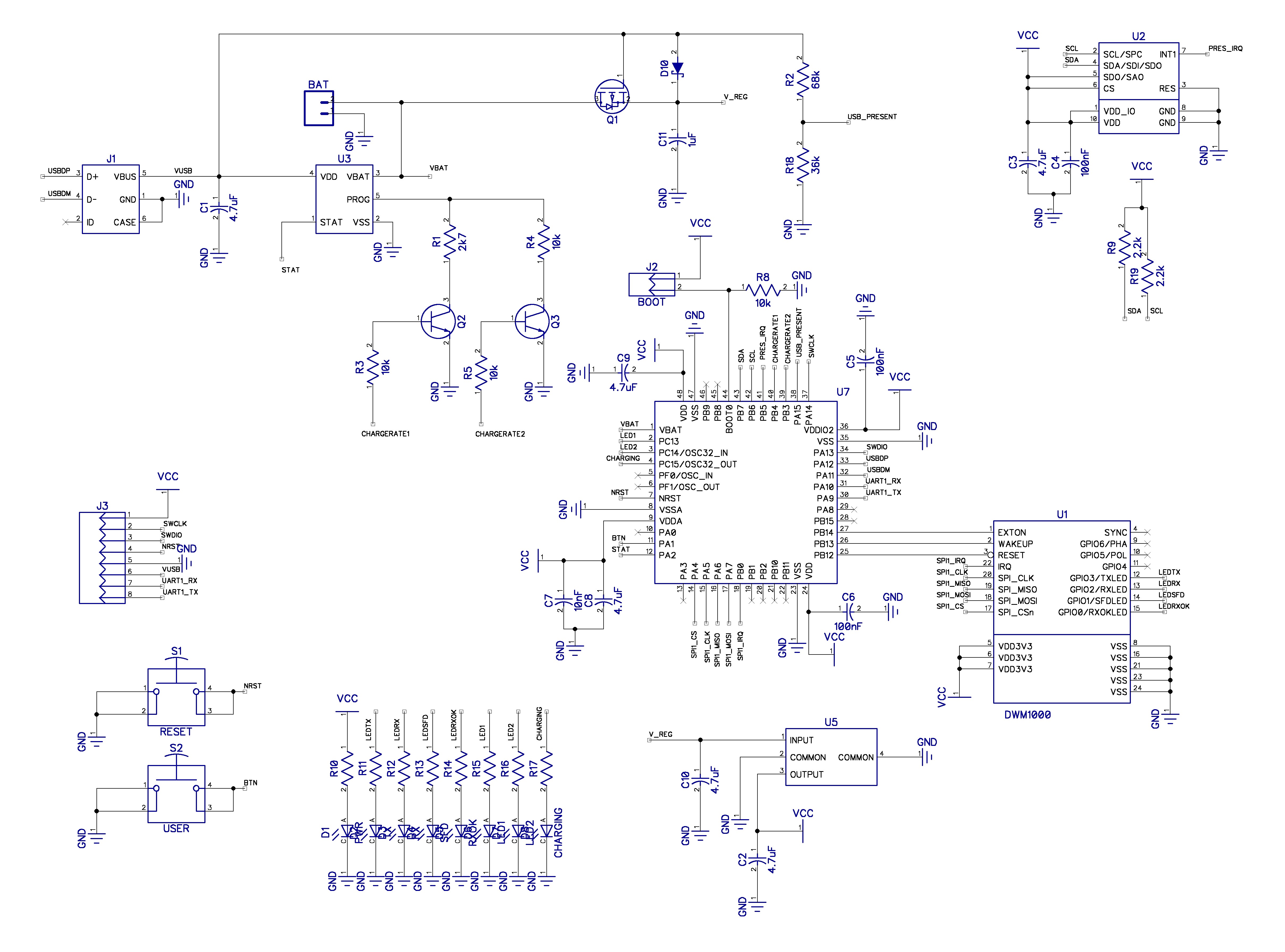
===The Tags=== | ===The Tags=== | ||
| − | + | [[File:Tag_layout.png|600px|thumb|right|Tag layout]] | |
The tag schematic can be seen at [[Media:Tag_sch.jpg|Tag schematic]] | The tag schematic can be seen at [[Media:Tag_sch.jpg|Tag schematic]] | ||
| − | + | The tags contains at least two known hardware errors, one is the missing load sharing in the charger design (see the anchors for the proper design), and the other known issue, is the '''regout''' pin being connected to 3.3v instead of bypassed to ground through 100 nF capacitor. As with the anchors, the next hardware revision of the tags should implement a proper power scheme, through switch-mode regulators. | |
| − | + | ||
| − | + | ||
| + | TODO: Add some more content here about the tags, mention ST-Link/V2 and IMU for sensor fusion | ||
==Software== | ==Software== | ||
All the PCB design is done in a software suite called DipTrace, which can be downloaded for free at [http://diptrace.com/ www.diptrace.com]. The software is currently only available in a Windows and Mac OS X version, but runs perfectly through [[https://en.wikipedia.org/wiki/Wine_(software) Wine]]. DipTrace offers a free student license, allowing a larger design along with some extra features. This student license can be requested by writing an email to the contact address listed at their [http://diptrace.com/buy/academic/ academic] site. | All the PCB design is done in a software suite called DipTrace, which can be downloaded for free at [http://diptrace.com/ www.diptrace.com]. The software is currently only available in a Windows and Mac OS X version, but runs perfectly through [[https://en.wikipedia.org/wiki/Wine_(software) Wine]]. DipTrace offers a free student license, allowing a larger design along with some extra features. This student license can be requested by writing an email to the contact address listed at their [http://diptrace.com/buy/academic/ academic] site. | ||
Revision as of 14:12, 31 May 2016
This page describes the hardware design of the 3D localization system.
The anchors and tags are made up of some main components as described in the table below. The main difference is that the anchors have 180° of the antenna shielded in order to allow mounting on walls and ceilings without changing the antenna properties from reflections, other than that the tags contains a high precision IMU for sensor fusion in order to improve the velocity estimates.
| Anchors | Tag |
|---|---|
| a cortex-m0 processor from ST (STM32f072) | a cortex-m3 processor from ST (STM32f103) |
| an UWB device (DWM1000) | an UWB device (DWM1000) |
| a pressure sensor (LPS25H) | a pressure sensor (LPS25H) |
| a 3.3v low noise LDO regulator (MIC5209) | a high precision IMU (MPU-9250) |
| a single-cell LIPO charger (MCP73831) | a 3.3v low noise LDO regulator (MIC5209) |
| a single-cell LIPO charger (MCP73831) |
Contents |
Connectivity
The system contains a number of potential ways to extract information. It is possible to connect to the anchors through a UART serial port, a virtual serial port on the USB port, or SWD via eg. openOCD (GDB). In the same way the tags can be reached through the UART port, a virtual serial port through the USB port, SWD or I2C. The next generation of the tags are supposed to SPI extracted from the uC as well for improved connectivity to eg. a robot.
The Anchors

The anchor schematic can be seen at Anchor schematic
The anchor hardware is still error free, meaning that there is yet to be found errors in the newest electronic design. The only thing on the list of changes to come in the next revision is a better power control, courtesy of a switch-mode regulator and the ability to utilize the ultra-low power sleep mode of the DW1000 devices. This would allow the anchors to be powered on and off wirelessly, while still maintaining an ultra low power consumption in standby mode.
TODO: Add some more content here about the anchors, mention ST-Link/V2
The Tags

The tag schematic can be seen at Tag schematic
The tags contains at least two known hardware errors, one is the missing load sharing in the charger design (see the anchors for the proper design), and the other known issue, is the regout pin being connected to 3.3v instead of bypassed to ground through 100 nF capacitor. As with the anchors, the next hardware revision of the tags should implement a proper power scheme, through switch-mode regulators.
TODO: Add some more content here about the tags, mention ST-Link/V2 and IMU for sensor fusion
Software
All the PCB design is done in a software suite called DipTrace, which can be downloaded for free at www.diptrace.com. The software is currently only available in a Windows and Mac OS X version, but runs perfectly through [Wine]. DipTrace offers a free student license, allowing a larger design along with some extra features. This student license can be requested by writing an email to the contact address listed at their academic site.