Regnot settings for Robobot
(→Heading control) |
(→Heading control) |
||
| Line 58: | Line 58: | ||
[[File:heading_control_dialog.png]] | [[File:heading_control_dialog.png]] | ||
| − | Figure | + | Figure 3. Heading control parameters for OK turns at a velocity of about 0.6 m/s. |
A 60 degree turn with an acceleration limit of 1m/s^2 makes a turn like this: | A 60 degree turn with an acceleration limit of 1m/s^2 makes a turn like this: | ||
| Line 64: | Line 64: | ||
[[File:heading_ctrl_20_deg.png]] | [[File:heading_ctrl_20_deg.png]] | ||
| − | Figure | + | Figure 4. The dotted line is the resulting heading, the magenta line is the target heading (when not in a turn. The red curve is the mission line number in the script below. |
This curve is generated with the following script: | This curve is generated with the following script: | ||
Revision as of 21:42, 16 March 2017
This is some suggestions for changed settings for Robobot.
Contents |
Robot configuration
Metric setup
The distance between driving wheels are different from a Regbot.
Control issues
Some examples of control settings.
Edge control
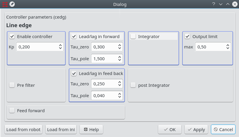
For higher speed in the range 0.7-0.9 m/s the following control settings could be used.
The control uses a Lag-controller to decrease the static gain by a factor 5 (a pole with a time constant of 1.5 sec and a zero with a time constant of 0.3 seconds). This means that the high frequency gain is Kp*0.3/1.5 = 0.06.
The gain is further scaled by the speed (from firmware version 604), so that the gain is reduced to half at 0.5m/s, but the filter times are maintained. This is probably a bad solution, as the response probably is more distance driven than time driven.
A test script to could be:
thread=1
   vel=0.01, acc=5.0, log=50.0: time=0.2
   vel=0.9, edger=1, white=0: dist=10.0, xb=20
   vel=0,event=7 : xb<10
   :vel< 0.1
   vel=-0.3,tr=0.1:turn=60
   vel=0.3,tr=0.1:turn=60
   vel=-0.3,tr=0.1:turn=60
   vel=0.7, edger=-1, white=0: dist=10.0, xb=20, log=0
The mission follows right side of line,
- in a left curve (1mØ) until crossing a line
- wait for crossing line to disappear,
- and velocity reach 0
- make a 3-point 180 degree turn
- follow the other side of line - now a right curve (until log is full or 10 meters or crossing another black line)
The difference between a left and a right curve is the "edger=1.0" and "edger=-1.0", this makes the robot follow the curve with an offset of 1cm towards the center of the curve (more left in a left curve). This gives more space for overshoot when hitting the curve - the sensor range is about +/- 2cm.
If the line is no longer valid, then the last curvature is maintained, i.e. there is a chance that the the line will be re-found.
Heading control
Heading control is not used during a tr=xx based turn, but after such a turn the heading control maintains the end heading. The end heading is the start heading plus the turned angle.
While driving straight, then the heading control attempts to keep the heading.
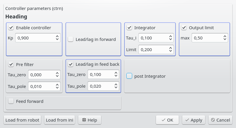
Heading control is somewhat speed dependent, these paramaters seems to be good at about 0.6 m/s.
Figure 3. Heading control parameters for OK turns at a velocity of about 0.6 m/s.
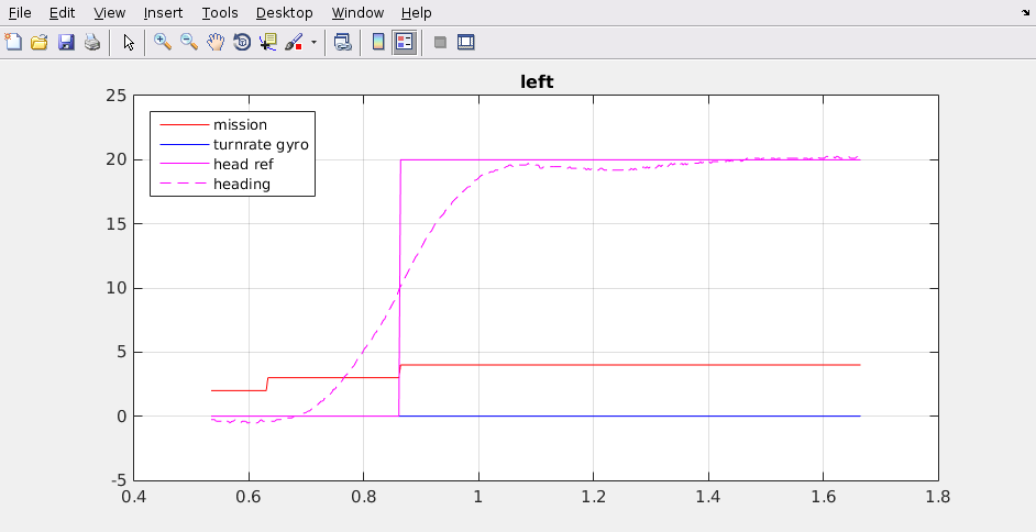
A 60 degree turn with an acceleration limit of 1m/s^2 makes a turn like this:
Figure 4. The dotted line is the resulting heading, the magenta line is the target heading (when not in a turn. The red curve is the mission line number in the script below.
This curve is generated with the following script:
thread=6
   : time=0.01
   vel=0.6, acc=1.0: dist=0.1,time=1
   log=3.0: time=0.1
   tr=0.2: turn=20.0
   : dist=0.3, log=0
This is after version 3.612 (from 16 March 2017.


