24V switch
From Rsewiki
(Difference between revisions)
(Created page with " Switch - intended for a 24V motor with no more than 3-4A continuous current The box has a microprocessor controllable with a simple set of commands. power on power off p...") |
|||
| Line 13: | Line 13: | ||
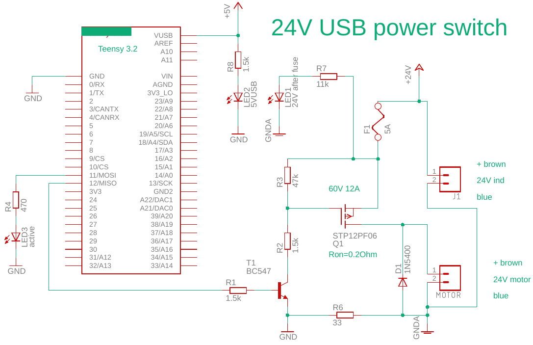
The schematic is as in figure 1. | The schematic is as in figure 1. | ||
| − | [[File: | + | [[File:24V_usb_power_switch.png]] |
Figure 1. Schematics for 24V switch. The teensy is a 3.2 (the pin layout is here for a teensy 3.5). The MOSFET is mounted on the PCB, but 1W (5A) should be OK. The fuse is an automotive-fuse, that could be replaced with 10A if close to 5A use. | Figure 1. Schematics for 24V switch. The teensy is a 3.2 (the pin layout is here for a teensy 3.5). The MOSFET is mounted on the PCB, but 1W (5A) should be OK. The fuse is an automotive-fuse, that could be replaced with 10A if close to 5A use. | ||
Revision as of 08:02, 14 October 2018
Switch - intended for a 24V motor with no more than 3-4A continuous current
The box has a microprocessor controllable with a simple set of commands.
power on
power off
power
help
Help shows the list of commands, when using e.g. putty as a client.
The schematic is as in figure 1.
 Figure 1. Schematics for 24V switch. The teensy is a 3.2 (the pin layout is here for a teensy 3.5). The MOSFET is mounted on the PCB, but 1W (5A) should be OK. The fuse is an automotive-fuse, that could be replaced with 10A if close to 5A use.