Wheel encoder
(→Board) |
(→Battery) |
||
| Line 38: | Line 38: | ||
====Battery==== | ====Battery==== | ||
| − | The battery voltage divider uses a 27kOhm and a 1.2kOhm, allowing up to 28.2V to be measured. (in (optional) ground connection is mounted a 100 Ohm resistor to avoid or limit | + | The battery voltage divider uses a 27kOhm and a 1.2kOhm, allowing up to 28.2V to be measured. (in (optional) ground connection is mounted a 100 Ohm resistor to avoid or limit any ground current). |
There is a filter capacitor of 390nF. | There is a filter capacitor of 390nF. | ||
Revision as of 17:10, 7 March 2019
Back to TerrainHopper
Contents |
Introduction
Wheel encoders are intended on all 4 motors, replacing the brake.
Initially rear motors are mounted with encoders. The encoders are of type AS5057 12 bit magnetic encoders.
Additionally encoder A and B signals are forwarded, but not enabled.
Board
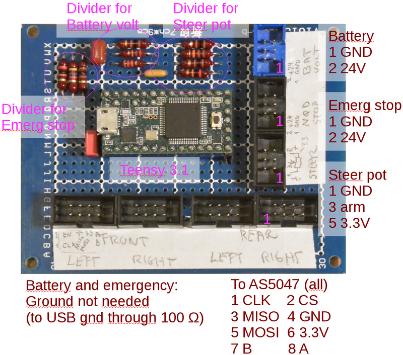
Encoder interface is I2C and interfaced using a Teensy 3.1 processor, as shown in figure 1.
Figure 1. Breadboard with Teensy 3.1 and 4 8-pin connectors to the AS5047 boards. The board also holds the needed voltage dividers for battery voltage and steering potentiometer.
Encoder interface
Signal wires to encoders has a 100 Ohm serial resistor (CLK, MISO, MOSI (and CS on rear encoders))
- pin 1: CLK (green-white)
- pin 2: Chip select (green)
- pin 3: MISO (orange-white)
- pin 4: GND (blue)
- pin 5: MOSI (blue-white)
- pin 6: 3.3V (orange)
- pin 7: B quadrature signal (brown-white)
- pin 8: A quadrature signal (brown)
Wires using unshielded network cable (cat-5)
Voltage dividers
The Teensy AD converter for battery voltage and steering potentiometer uses 1.2V reference. The signals therefore needs voltage dividers.
Battery
The battery voltage divider uses a 27kOhm and a 1.2kOhm, allowing up to 28.2V to be measured. (in (optional) ground connection is mounted a 100 Ohm resistor to avoid or limit any ground current). There is a filter capacitor of 390nF.
Steering potentiometer
The steering potentiometer is supplied from 3.3V supply (through 100 Ohm resistors). The arm is then voltage divided using a 20kOhm and 11kOhm resistors, with a filter capacitor of 330nF.
Emergency stop
This is intended to inform software that emergency stop is pressed - pt. only one channel for rear emergency stop, but maybe the remote should be separate.
A voltage divider is added on the emergency line with 20kOhm and 4.7kOhm, this should give a switch voltage of about 7V - assuming supply from 24 V.
