Wheel encoder
(→Debug output) |
(→Debug output) |
||
| Line 78: | Line 78: | ||
=== Debug output === | === Debug output === | ||
| − | The Teensy constantly blinks | + | The Teensy constantly blinks its LED every second. |
The output should look something like: | The output should look something like: | ||
Revision as of 10:52, 21 June 2019
Back to TerrainHopper
Contents |
Introduction
Wheel encoders are intended on all 4 motors, replacing the brake.
Initially rear motors are mounted with encoders. The encoders are of type AS5057 12 bit magnetic encoders.
Additionally encoder A and B signals are forwarded, but not enabled.
Board
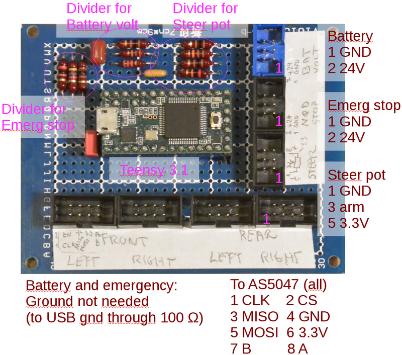
Encoder interface is I2C and interfaced using a Teensy 3.1 processor, as shown in figure 1.
Figure 1. Breadboard with Teensy 3.1 and 4 8-pin connectors to the AS5047 boards. The board also holds the needed voltage dividers for battery voltage and steering potentiometer.
FRONT-RIGHT is changed to be steering encoder (may 2019).
Encoder interface
Signal wires to encoders has a 100 Ohm serial resistor (CLK, MISO, MOSI (and CS on rear encoders))
- pin 1: CLK (green-white)
- pin 2: Chip select (green)
- pin 3: MISO (orange-white)
- pin 4: GND (blue)
- pin 5: MOSI (blue-white)
- pin 6: 3.3V (orange)
- pin 7: B quadrature signal (brown-white)
- pin 8: A quadrature signal (brown)
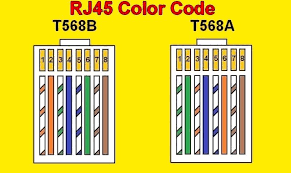
Wires using unshielded network cable (cat-5)
NB! some network cables have different color coding in the rj45 side of the connector. The coding above conforms to T568A, but the cables used on the terrainhopper uses T568B,
but as long as both cables are the same, then it should be OK.
Connection to Teensy
CLK  on all ports -> 100 Ohm -> pin 14 (CLK) on Teensy
MISO on all ports -> 100 Ohm -> pin  8 (DIN)
MOSI on all ports -> 100 Ohm -> pin  7 (DOUT)
3.3V on all ports to pin 3.3V on Teensy
Chip select:
Rear Right -> 100 Ohm -> pin 9
Rear Left  -> 100 Ohm -> pin 15
Steer      -> 0 Ohm -> pin 20
Front Left -> 0 Ohm -> pin 21
Encoder A, B
Rear Right -> 0 Ohm -> pin 18 (A), 17 (B)
Rear Left  -> 0 Ohm -> pin  4 (A),  5 (B)
Steer      -> 0 Ohm -> pin  2 (A),  3 (B)
Front Left -> 0 Ohm -> pin  0 (A),  1 (B)
Voltage dividers
The Teensy AD converter for battery voltage and steering potentiometer uses 1.2V reference. The signals therefore needs voltage dividers.
Battery
The battery voltage divider uses a 27kOhm and a 1.2kOhm, allowing up to 28.2V to be measured. (in (optional) ground connection is mounted a 100 Ohm resistor to avoid or limit any ground current). There is a filter capacitor of 390nF.
Connected to pin (23) A9 on Teensy
Steering potentiometer
The steering potentiometer is supplied from 3.3V supply (through 100 Ohm resistors). The arm is then voltage divided using a 20kOhm and 11kOhm resistors, with a filter capacitor of 330nF.
Potentiometer arm is connected to pin (19) A5 on Teensy.
Debug output
The Teensy constantly blinks its LED every second.
The output should look something like:
$ cat /dev/ttyACM0
enc 3.3 0 1  7907 54  1747 60 2740 1 1 0 0 805364
enc 3.3 0 1  7908 54  1748 60 2741 1 1 0 0 805372
enc 3.3 0 1  7908 54  1745 60 2740 1 1 0 0 805380
enc 3.3 0 1  7908 54  1752 60 2741 1 1 0 0 805388
enc 3.3 0 1  7908 54  1747 60 2741 1 1 0 0 805396
enc 3.3 0 1  7907 54  1748 60 2740 1 1 0 0 805403
enc 3.3 0 1  7908 54  1748 60 2741 1 1 0 0 805411
enc 3.3 0 1  7908 54  1748 60 2740 1 1 0 0 805419
enc 3.3 0 1  7907 54  1749 60 2741 1 1 0 0 805427
messages has this format:
enc : keyword
3.3 : intended for battery voltage (V)  (connected to 3.3V output of teensy - not used)
0   : emergency switch (1=24V)          (not connected)
1   : value from steering potentiometer (value 1 is a bit odd - not used)
7907: encoder rear left
54  : magnet distance rear left (fine)
1747: encoder rear right
60  : magnet distance rear right (fine)
2740: encoder value steering (not stable in this printout)
1   : valid value (as5045 steering)
1   : ocf from 5045 init OK
0   : cof from 5045 no overflow if 0
0   : lin from 5045 no liniarity problems if 0
805364 : time in ms since Teensy start
Line ends with a linefeed and carriage return
Emergency stop
This is intended to inform software that emergency stop is pressed - pt. only one channel for rear emergency stop, but maybe the remote should be separate.
A voltage divider is added on the emergency line with 20kOhm and 4.7kOhm, this should give a switch voltage of about 7V - assuming supply from 24 V.
Connected to pin 22 (A8) on Teensy.

