Robobot
(→Installation instructions) |
(→Overview) |
||
| (140 intermediate revisions by one user not shown) | |||
| Line 1: | Line 1: | ||
This page is for ROBOBOT, an extension of REGBOT with a raspberry pi and three wheels. | This page is for ROBOBOT, an extension of REGBOT with a raspberry pi and three wheels. | ||
| − | [[File:onshape-view.png|400px]] [[File: | + | <!--[[File:onshape-view.png|400px]] --> |
| + | [[File:robobot_v5.png|400px]] | ||
| + | [[File:melina_b.jpg|250px]] | ||
| + | [[File:model-black.jpg | 450px]] | ||
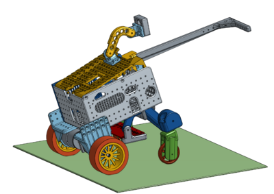
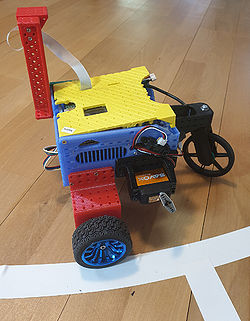
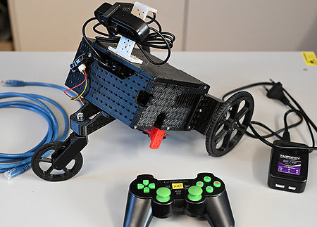
| − | Figure 1. Robobot | + | Figure 1. Robobot, The robot is a 3D-printed box with wheels and some electronics. |
| + | The third, fourth and fifth generations are shown here. | ||
| + | The 3D printed parts can be found here https://cad.onshape.com/documents/fef8699fcafb8aea780c8981/w/ce38e7fdd6cf8533b65e2c3c/e/4792e876b254f8e35059f863 | ||
== Overview == | == Overview == | ||
| + | |||
| + | Note: Not valid (mostly) for the 2024 version of the robot | ||
| + | |||
| + | ===hardware === | ||
| + | |||
| + | |||
| + | ROBOBOT is based on a navigation box with a line sensor (Edge sensor), an IR distance sensor and possibly some servos, all controlled by a microprocessor. | ||
| + | For more intelligent behaviour and more sensors, there is a Raspberry Pi in the box too, | ||
| + | |||
| + | The motors are JGB37-545 with an encoder and a 1:10 gearing (up to about 400RPM (or ~6 RPS (rotations per second) on the output axle). | ||
| + | |||
| + | There is a video introduction and demo here https://www.youtube.com/watch?v=6dNr_F0dsHw (from 2022 - slight changes since) | ||
| + | |||
| + | === Navigation box overview=== | ||
[[File:robobot-overview.png | 500px]] | [[File:robobot-overview.png | 500px]] | ||
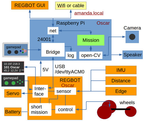
| − | Figure 2. ROBOBOT is an extension of the | + | Figure 2. ROBOBOT is an extension of the robot REGBOT. The REGBOT part controls the wheels and interfaces to the sensors, like an IMU (6-axis accelerometer and gyro), IR distance sensors (2), and a line edge detector. The REGBOT further controls up to 5 servos and controls the battery supply. ROBOBOT is further equipped with a Raspberry Pi to allow more complicated missions. The Raspberry Pi runs an interface process called "Bridge" and is the main interface to the REGBOT. The mission process collects data from the bridge and the REGBOT and supplies small mission code snippets to be executed by the REGBOT part. The mission process may use the camera and the Open-CV library functions. The speaker allows debugging messages or other sound effects. |
The ROBOBOT functions are available on the net at port number 24001. The existing user interface for REGBOT can access REGBOT functions from this port. | The ROBOBOT functions are available on the net at port number 24001. The existing user interface for REGBOT can access REGBOT functions from this port. | ||
| − | The gamepad can take | + | The gamepad can take control of the robot if the mission fails and can be used to initiate missions or other functions. |
| − | + | ==Software description== | |
| − | |||
| − | + | === Bridge software === | |
| − | + | ||
| − | + | ||
| − | + | The Robobot bridge runs on the Raspberry Pi and is started when the Raspberry Pi starts, with initial commands from an initialization file (bridge.ini). | |
| − | + | [[Robobot_bridge]] overview | |
| − | + | A bridge autostart feature is implemented in the script 'start_bridge.sh' in the home directory of the user 'local'. | |
| + | The is executed after a reboot. | ||
| − | + | The script can be amended with other commands that should be started after a reboot. | |
| − | + | === Mission software === | |
| − | + | The mission application is the primary user control for the robot. | |
| − | + | [[Robobot mission]] application overview. | |
| − | + | The Mission application is started manually from an ssh console or added to the reboot script 'start_bridge.sh'. | |
| + | <!-- | ||
| + | ===Python interface=== | ||
| − | + | A python-based control example - including especially camera streaming and interface. | |
| − | + | ||
| − | + | [[Python interface]] | |
| + | --> | ||
| − | == | + | ==Setup issues== |
| − | + | ===Installation instructions=== | |
| − | + | This installation should be done already, to update see next section. | |
| − | + | ||
| − | + | ||
| − | + | ||
| − | + | ||
| − | + | [[Raspberry and ROS]] (not finished) | |
| − | + | [[Network setup]] (Wifi) | |
| − | + | [[Robobot camera]] camera setup | |
| − | + | ||
| − | + | ||
| − | + | ||
| − | + | ||
| − | + | ||
| − | + | ||
| − | + | ||
| − | + | ||
| − | + | [[Access from Windows]] and Linux to Raspberry files (and graphics) | |
| − | + | [[Other windows tools]] - show Raspberry Pi graphics in Windows (usually very very slow) | |
| − | + | [[Regbot GUI]] python setup and GUI install | |
| − | + | See [[Regbot calibration]] for sensor calibration. | |
| + | |||
| + | ===Software update=== | ||
| + | |||
| + | Update of the maintained software is on the SVN (subversion) repository. | ||
| + | |||
| + | SSH to the robot and go to these directories and do an update | ||
| + | |||
| + | cd | ||
| + | svn up svn/fejemis/ROS/catkin_ws/src/bridge | ||
| + | svn up svn/robobot | ||
| + | svn up svn/regbot | ||
| + | |||
| + | An update could look like this | ||
| + | $ svn up svn/fejemis/ROS/catkin_ws/src/bridge | ||
| + | Updating 'svn/fejemis/ROS/catkin_ws/src/bridge': | ||
| + | U fejemis/ROS/catkin_ws/src/bridge/udataitem.h | ||
| + | U fejemis/ROS/catkin_ws/src/bridge/ujoy.cpp | ||
| + | Updated to revision 228. | ||
| + | |||
| + | NB! this may cause a conflict if some of the files are changed locally. | ||
| + | Look at the filename and if it is not one of yours, then reply 'tc' (short for their conflict solution) | ||
| + | |||
| + | =====Compile on bridge changes===== | ||
| + | |||
| + | If there are updated files for the bridge, then | ||
| + | |||
| + | cd | ||
| + | cd catkin_ws | ||
| + | catkin_make | ||
| + | |||
| + | =====Compile and upload on Teensy changes===== | ||
| + | |||
| + | cd | ||
| + | cd svn/regbot/regbot/4.1 | ||
| + | make -j3 | ||
| + | |||
| + | This makes a file "regbot.hex" that is then to be loaded as the new firmware on the Teensy processor. | ||
| + | |||
| + | There is a script that can do that from the command line: | ||
| + | |||
| + | ./upload.sh | ||
| + | |||
| + | It will say something like | ||
| + | |||
| + | $ ./upload.sh | ||
| + | Teensy Loader, Command Line, Version 2.2 | ||
| + | Read "regbot.hex": 314368 bytes, 3.9% usage | ||
| + | Waiting for Teensy device... | ||
| + | (hint: press the reset button) | ||
| + | |||
| + | Press and hold the "POWER ON" and then press the button on the Teensy board. | ||
| + | |||
| + | The "POWER ON" button maintains power to the Raspberry Pi and the Teensy while uploading. | ||
| + | |||
| + | It will likely fail the first time but keep pressing "POWER ON" and repeat the command, and it should now say | ||
| + | |||
| + | $ ./upload.sh | ||
| + | Teensy Loader, Command Line, Version 2.2 | ||
| + | Read "regbot.hex": 314368 bytes, 3.9% usage | ||
| + | Found HalfKay Bootloader | ||
| + | Programming............................. | ||
| + | Booting | ||
| + | |||
| + | If you released the "POWER ON" in the process, the Raspberry Pi would power down. You then need to hold the "POWER ON" until the Raspberry has booted; you then re-login and rerun the script. | ||
| + | |||
| + | =====Make the upload.sh===== | ||
| + | |||
| + | If you have the "upload.sh", this step is not needed. | ||
| + | |||
| + | The command line upload is described here https://www.pjrc.com/teensy/loader_cli.html . | ||
| + | |||
| + | On a Raspberry you first need to install a USB library: | ||
| + | |||
| + | sudo apt install libusb-dev | ||
| + | |||
| + | Then get the code: | ||
| + | |||
| + | cd ~/git | ||
| + | git clone https://github.com/PaulStoffregen/teensy_loader_cli.git | ||
| + | cd teensy_loader_cli | ||
make | make | ||
| − | |||
| − | + | You should now have a "teensy_loader_cli" file; copy this to the svn/regbot/regbot/4.1 directory | |
| − | + | cp teensy_loader_cli ~/svn/regbot/regbot/4.1/ | |
| − | + | ||
| − | + | Make the "upload.sh" script | |
| − | + | cd ~/svn/regbot/regbot/4.1 | |
| + | nano upload.sh | ||
| − | + | Insert the following into the script: | |
| − | + | ||
| − | + | ||
| − | + | ||
| − | + | #!/bin/bash | |
| + | ./teensy_loader_cli -v -w --mcu=TEENSY41 regbot.hex | ||
| − | + | Save with ctrl-s and exit with ctrl-x | |
| − | + | Make the script executable | |
| − | + | chmod +x upload.sh | |
| − | + | == old instructions == | |
| − | + | Partially valid only. | |
| − | + | [[Install on raspberry]] on a clean SD-card - raspi-config. | |
| + | |||
| + | [[Setup user local]] adding a new user. | ||
| + | |||
| + | [[Linux tools]] - packages to install. | ||
| + | |||
| + | [[Access from PC]] (Linux or Windows). | ||
| + | |||
| + | [[Other windows tools]] - run graphics from Windows | ||
| + | |||
| + | [[Instructions for getting started]] - primarily network, Linux intro and wifi setup. | ||
| + | |||
| + | <!-- [[Full installation instructions]] - like Linux itself, sound and camera and how to connect the Raspberry disk to Windows and Linux computers. --> | ||
| + | |||
| + | ==REGBOT setup == | ||
| + | |||
| + | Several parameters in the REGBOT part of the robot need setting. | ||
| + | |||
| + | Some suggestions are provided here using the REGBOT GUI (available on the raspberry in the 'regbotgui' directory, and in a Windows version): | ||
| + | |||
| + | [[Regbot settings]] | ||
| − | + | === Hardware === | |
| − | + | The Robobot frame is 3D printed, the design is in onshape - see this link https://cad.onshape.com/documents/fef8699fcafb8aea780c8981/w/ce38e7fdd6cf8533b65e2c3c/e/4792e876b254f8e35059f863 , in the list of parts to the left it is possible to export (right-click) as STL files, that you can slice for your 3D printer. | |
| − | == | + | === Navigation box assembly === |
| − | + | There are video-instructions on the course page. | |
Revision as of 15:16, 28 February 2024
This page is for ROBOBOT, an extension of REGBOT with a raspberry pi and three wheels.
Figure 1. Robobot, The robot is a 3D-printed box with wheels and some electronics. The third, fourth and fifth generations are shown here. The 3D printed parts can be found here https://cad.onshape.com/documents/fef8699fcafb8aea780c8981/w/ce38e7fdd6cf8533b65e2c3c/e/4792e876b254f8e35059f863
Contents |
Overview
Note: Not valid (mostly) for the 2024 version of the robot
hardware
ROBOBOT is based on a navigation box with a line sensor (Edge sensor), an IR distance sensor and possibly some servos, all controlled by a microprocessor. For more intelligent behaviour and more sensors, there is a Raspberry Pi in the box too,
The motors are JGB37-545 with an encoder and a 1:10 gearing (up to about 400RPM (or ~6 RPS (rotations per second) on the output axle).
There is a video introduction and demo here https://www.youtube.com/watch?v=6dNr_F0dsHw (from 2022 - slight changes since)
Figure 2. ROBOBOT is an extension of the robot REGBOT. The REGBOT part controls the wheels and interfaces to the sensors, like an IMU (6-axis accelerometer and gyro), IR distance sensors (2), and a line edge detector. The REGBOT further controls up to 5 servos and controls the battery supply. ROBOBOT is further equipped with a Raspberry Pi to allow more complicated missions. The Raspberry Pi runs an interface process called "Bridge" and is the main interface to the REGBOT. The mission process collects data from the bridge and the REGBOT and supplies small mission code snippets to be executed by the REGBOT part. The mission process may use the camera and the Open-CV library functions. The speaker allows debugging messages or other sound effects.
The ROBOBOT functions are available on the net at port number 24001. The existing user interface for REGBOT can access REGBOT functions from this port.
The gamepad can take control of the robot if the mission fails and can be used to initiate missions or other functions.
Software description
Bridge software
The Robobot bridge runs on the Raspberry Pi and is started when the Raspberry Pi starts, with initial commands from an initialization file (bridge.ini).
Robobot_bridge overview
A bridge autostart feature is implemented in the script 'start_bridge.sh' in the home directory of the user 'local'. The is executed after a reboot.
The script can be amended with other commands that should be started after a reboot.
Mission software
The mission application is the primary user control for the robot.
Robobot mission application overview.
The Mission application is started manually from an ssh console or added to the reboot script 'start_bridge.sh'.
Setup issues
Installation instructions
This installation should be done already, to update see next section.
Raspberry and ROS (not finished)
Network setup (Wifi)
Robobot camera camera setup
Access from Windows and Linux to Raspberry files (and graphics)
Other windows tools - show Raspberry Pi graphics in Windows (usually very very slow)
Regbot GUI python setup and GUI install
See Regbot calibration for sensor calibration.
Software update
Update of the maintained software is on the SVN (subversion) repository.
SSH to the robot and go to these directories and do an update
cd
svn up svn/fejemis/ROS/catkin_ws/src/bridge
svn up svn/robobot
svn up svn/regbot
An update could look like this
$ svn up svn/fejemis/ROS/catkin_ws/src/bridge
Updating 'svn/fejemis/ROS/catkin_ws/src/bridge':
U    fejemis/ROS/catkin_ws/src/bridge/udataitem.h
U    fejemis/ROS/catkin_ws/src/bridge/ujoy.cpp
Updated to revision 228.
NB! this may cause a conflict if some of the files are changed locally. Look at the filename and if it is not one of yours, then reply 'tc' (short for their conflict solution)
Compile on bridge changes
If there are updated files for the bridge, then
cd
cd catkin_ws
catkin_make
Compile and upload on Teensy changes
cd
cd svn/regbot/regbot/4.1
make -j3
This makes a file "regbot.hex" that is then to be loaded as the new firmware on the Teensy processor.
There is a script that can do that from the command line:
./upload.sh
It will say something like
$ ./upload.sh
Teensy Loader, Command Line, Version 2.2
Read "regbot.hex": 314368 bytes, 3.9% usage
Waiting for Teensy device...
 (hint: press the reset button)
Press and hold the "POWER ON" and then press the button on the Teensy board.
The "POWER ON" button maintains power to the Raspberry Pi and the Teensy while uploading.
It will likely fail the first time but keep pressing "POWER ON" and repeat the command, and it should now say
$ ./upload.sh
Teensy Loader, Command Line, Version 2.2
Read "regbot.hex": 314368 bytes, 3.9% usage
Found HalfKay Bootloader
Programming.............................
Booting
If you released the "POWER ON" in the process, the Raspberry Pi would power down. You then need to hold the "POWER ON" until the Raspberry has booted; you then re-login and rerun the script.
Make the upload.sh
If you have the "upload.sh", this step is not needed.
The command line upload is described here https://www.pjrc.com/teensy/loader_cli.html .
On a Raspberry you first need to install a USB library:
sudo apt install libusb-dev
Then get the code:
cd ~/git
git clone https://github.com/PaulStoffregen/teensy_loader_cli.git
cd teensy_loader_cli
make
You should now have a "teensy_loader_cli" file; copy this to the svn/regbot/regbot/4.1 directory
cp teensy_loader_cli ~/svn/regbot/regbot/4.1/
Make the "upload.sh" script
cd ~/svn/regbot/regbot/4.1
nano upload.sh
Insert the following into the script:
#!/bin/bash
./teensy_loader_cli -v -w --mcu=TEENSY41 regbot.hex
Save with ctrl-s and exit with ctrl-x
Make the script executable
chmod +x upload.sh
old instructions
Partially valid only.
Install on raspberry on a clean SD-card - raspi-config.
Setup user local adding a new user.
Linux tools - packages to install.
Access from PC (Linux or Windows).
Other windows tools - run graphics from Windows
Instructions for getting started - primarily network, Linux intro and wifi setup.
REGBOT setup
Several parameters in the REGBOT part of the robot need setting.
Some suggestions are provided here using the REGBOT GUI (available on the raspberry in the 'regbotgui' directory, and in a Windows version):
Hardware
The Robobot frame is 3D printed, the design is in onshape - see this link https://cad.onshape.com/documents/fef8699fcafb8aea780c8981/w/ce38e7fdd6cf8533b65e2c3c/e/4792e876b254f8e35059f863 , in the list of parts to the left it is possible to export (right-click) as STL files, that you can slice for your 3D printer.
There are video-instructions on the course page.


