Flexbot
(→Information) |
|||
| (57 intermediate revisions by 3 users not shown) | |||
| Line 1: | Line 1: | ||
| + | |||
=Introduction= | =Introduction= | ||
| + | This is the main page of Flexbot. Here you will find all information and instructions related to the Flexbot project. | ||
| + | |||
| + | [[File:Flexbot-rendered-115678 gi tonemapped reinhard05.png | 400px]] | ||
| + | <!--[[File:underben-screenshot.png]]--> | ||
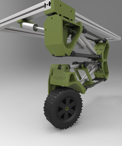
| − | + | Figure 1. Nice model of a Flexbot leg. The green parts are the main joints, foot, knee and hip. The black tubes are 16mm carbon fibre tubes, at the ends there are black plastic blocks, that connects the tube to the joint axle. The aluminium colourized parts are actuators and the base frame of the robot. The layout of the main joints are slightly outdated. | |
| − | + | =Information= | |
| + | [[Repository | GIT repository, documents, drawings and software.]] | ||
| − | + | [[flexbot_design| Leg main geometry.]] | |
| − | + | [[Flexbot_parts_list | Leg components, electric design, PCB, schematic and firmware]] - PCB layout and part numbers. | |
| − | + | [[mavlink| MAVLink communication protocol ]] | |
| − | + | ||
| − | + | ||
| − | + | ||
| − | + | ||
| − | + | ||
| − | + | [[Web status page]] for robot. | |
| − | + | [[3D camera]] from Intel D400 series | |
| − | + | ||
| − | + | ||
| − | + | [[Robot installation]] - main processor software | |
| − | + | [[Web Interface]] - Interface for ROS and browser | |
| − | + | ||
| − | + | ||
| − | + | ||
| − | + | ||
| − | + | ||
| − | + | ||
| − | = | + | =Other (older) pages= |
| − | + | [[Flexbot older pages | Assemble instructions and older software and plans]] | |
| − | + | ||
| − | + | ||
| − | + | ||
| − | + | ||
| − | + | ||
| − | |||
| − | + | ---- | |
| − | + | ||
| − | + | ||
| − | |||
| − | + | --[[User:Jca|Jca]] ([[User talk:Jca|talk]]) 12:57, 9 June 2018 (CEST) | |
| − | + | ||
| − | + | ||
| − | + | ||
| − | + | ||
| − | + | ||
| − | + | ||
| − | + | ||
| − | + | ||
| − | + | ||
| − | + | ||
| − | + | ||
| − | + | ||
| − | + | ||
| − | + | ||
| − | + | ||
| − | + | ||
Latest revision as of 15:22, 15 January 2020
[edit] Introduction
This is the main page of Flexbot. Here you will find all information and instructions related to the Flexbot project.
Figure 1. Nice model of a Flexbot leg. The green parts are the main joints, foot, knee and hip. The black tubes are 16mm carbon fibre tubes, at the ends there are black plastic blocks, that connects the tube to the joint axle. The aluminium colourized parts are actuators and the base frame of the robot. The layout of the main joints are slightly outdated.
[edit] Information
GIT repository, documents, drawings and software.
Leg components, electric design, PCB, schematic and firmware - PCB layout and part numbers.
MAVLink communication protocol
Web status page for robot.
3D camera from Intel D400 series
Robot installation - main processor software
Web Interface - Interface for ROS and browser
[edit] Other (older) pages
Assemble instructions and older software and plans
