Flexbot design
From Rsewiki
(Difference between revisions)
(→Design overview hardware) |
(→Design overview hardware) |
||
| Line 3: | Line 3: | ||
* An angled DC motor to control the wheel. | * An angled DC motor to control the wheel. | ||
* Two linear actuators to control the motion of the robot's body. | * Two linear actuators to control the motion of the robot's body. | ||
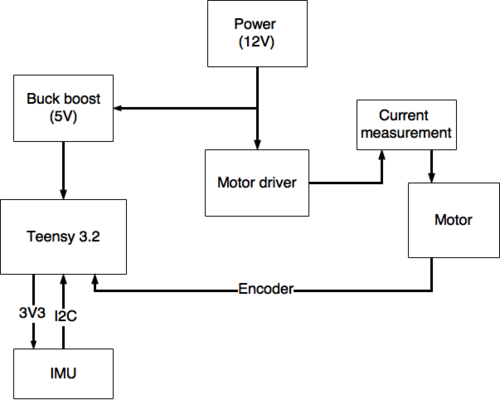
| − | Each of these actuators is controlled by a μ-processor board (Teensy 3.2). The Teensy controls the actuators either directly or via a motor driver and receives feedback from the actuators encoder signals. | + | Each of these actuators is controlled by a μ-processor board (Teensy 3.2). The Teensy controls the actuators either directly or via a motor driver and receives feedback from the actuators encoder signals. A general hardware block diagram for a Teensy configuration is shown in Figure 1. |
[[File:Flexbot_teensy_hardware_blockdiagram.png | 500px]] | [[File:Flexbot_teensy_hardware_blockdiagram.png | 500px]] | ||
| − | Figure 1: | + | Figure 1: General hardware block diagram of the Teensy configuration. |
Revision as of 09:22, 26 June 2017
Design overview hardware
Each "leg" of the flexbot consists of 3 actuators.
- An angled DC motor to control the wheel.
- Two linear actuators to control the motion of the robot's body.
Each of these actuators is controlled by a μ-processor board (Teensy 3.2). The Teensy controls the actuators either directly or via a motor driver and receives feedback from the actuators encoder signals. A general hardware block diagram for a Teensy configuration is shown in Figure 1.
Figure 1: General hardware block diagram of the Teensy configuration.
