Inspection robot
(→Hardware) |
|||
| Line 1: | Line 1: | ||
Installation and use noted for 6-legged inspection robot. | Installation and use noted for 6-legged inspection robot. | ||
| + | ==Mobotware on a Raspberry== | ||
| + | |||
| + | Installation - see How-to guide on main page. | ||
==Servo with feedback== | ==Servo with feedback== | ||
Revision as of 17:19, 1 May 2015
Installation and use noted for 6-legged inspection robot.
Contents |
Mobotware on a Raspberry
Installation - see How-to guide on main page.
Servo with feedback
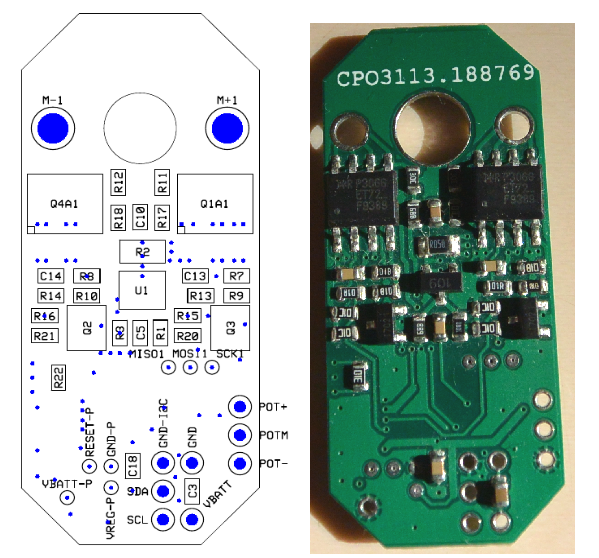
The servo software is build upon the "Open servo" project, with a slightly modified PCB.
Hardware
- Potentiometer mount:
Green towards motor yellow center Red away from motor.
- or maybe more likely, motor is turned 180 deg.
- Power:
At least 6.5V - to allow regulator to give 5V
- Layout of servo-print with connections. Looks like Vbatt-P is connected to pot-, this can not be right?
Software
P value must be set to (about 50) to make servo run. This gives some overshoot for large steps. A D-value makes it worse.
Need to investigate control-part of servo.
Update rate seems to be slow (~10Hz) investigate.
EMF sense is not in software
Current has some reaction, but no reaction to load? - investigate.
RHD plugin
A new plugin is uploaded using USBISS converter to i2c - should be changed to i2c on target platform
Setting and main status for N servos (up to 24) implemented. Debug status for 1 servo implemented (first 48 registers are monitored)
Commands (write with register adress above 0x7f) is working
0x82 (130) enable PWM
0x83 (131) disable PWM
etc - see main.c in software
Change of i2c address is not implemented/tested (there is a save to eeprom command)
