3D localization
(→Connectivity) |
|||
| Line 1: | Line 1: | ||
| − | |||
| − | + | ||
| + | ==Hardware== | ||
The localization system at hand consists of at least 4 '''anchors''' and a '''tag'''. <br /> | The localization system at hand consists of at least 4 '''anchors''' and a '''tag'''. <br /> | ||
Each device communicates and ranges with each other through an UWB ([[Ultra Wide Band]]) radio. | Each device communicates and ranges with each other through an UWB ([[Ultra Wide Band]]) radio. | ||
Revision as of 10:42, 28 May 2016
Contents |
Hardware
The localization system at hand consists of at least 4 anchors and a tag.
Each device communicates and ranges with each other through an UWB (Ultra Wide Band) radio.
The anchors and tags are made up of some main components as described in the table below. The main difference is that the anchors have 180° of the antenna shielded in order to allow mounting on walls and ceilings without changing the antenna properties from reflections, other than that the tags contains a high precision IMU for sensor fusion in order to improve the velocity estimates.
| Anchors | Tag |
|---|---|
| a cortex-m0 processor from ST (STM32f072) | a cortex-m3 processor from ST (STM32f103) |
| an UWB device (DWM1000) | an UWB device (DWM1000) |
| a pressure sensor (LPS25H) | a pressure sensor (LPS25H) |
| a 3.3v low noise LDO regulator (MIC5209) | a high precision IMU (MPU-9250) |
| a single-cell LIPO charger (MCP73831) | a 3.3v low noise LDO regulator (MIC5209) |
| a single-cell LIPO charger (MCP73831) |
Connectivity
The system contains a number of potential ways to extract information. It is possible to connect to the anchors through a UART serial port, a virtual serial port on the USB port, or SWD via eg. openOCD (GDB). In the same way the tags can be reached through the UART port, a virtual serial port through the USB port or SWD. The next generation of the tags are supposed to have I2C and SPI extracted from the uC for improved connectivity to eg. a robot.
% TODO: Add some notes and a picture describing pinouts
Operation
Ranging
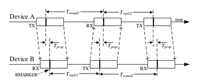
In order to estimate the distance between an anchor and a tag, the system uses Time of Flight (TOF). The time of flight scheme implemented in the system, is an infrastructure based asset tracking scheme based on asymmetric double-sided two way ranging (DS-TWR). In this ranging scheme the tag sends a Poll message as a broadcast, which is received by a number of anchors (three in this case) in the infrastructure. Each anchor then replies in successive responses with packets RespA, RespB & RespC after which the tag, sends the Final message as a broadcast again, received by all three anchors. This allows the tag to be located after sending only 2 messages and receiving 3 (including another 3 if the distances are needed on the tag).
This scheme is illustrated in the figure below. This represents a substantial saving in message traffic, thereby saving battery power and air-time, while increasing potential update rate.
Positioning
Limitations
The system does come with a few limitations, which will be discussed below.
Line of sight (LOS)
The most important limitation is that it is very sensitive to line of sight (LOS). This means that the tag trying to localize itself, should always have pure line of sight to at least 4 anchors, which is why it is recommended to run the system with 6 or more anchors, as this would give the system redundancy. It is possible to give a clue about whether the most recent range measurement was taken in a line of sight situation or not, by looking at the quality of the measurement. This quality is a combination of the received power level and the first path power level, and is discussed further in the DW1000 User manual on page 45.
Calibration and bias
Because the system is based on time of flight measurements of radio waves, even a small change in the time stamps of the system will result in huge variations in distance (1 ns results in a change of 299 mm). This means that proper calibration of the system is crucial in order to obtain any usable performance. The main calibration property of the system is the antenna delay constants, a constant describing the delay from antenna through PCB. A detailed explanation of the antenna delay and how to calibrate it properly can be found in APS014: Antennna Delay Calibration
