Robobot level 1
(→Pose) |
(→Drive control level) |
||
| Line 4: | Line 4: | ||
| − | |||
[[File:robobot_level_1.png | 800px]] | [[File:robobot_level_1.png | 800px]] | ||
| Line 11: | Line 10: | ||
The desired wheel velocity for each wheel is generated in the mixer from a desired linear and rotational velocity. | The desired wheel velocity for each wheel is generated in the mixer from a desired linear and rotational velocity. | ||
| − | + | == Hardware Teensy == | |
The Teensy handles all the sensors connected to the microprocessor and the wheel motors as well as the up to 5 servos. | The Teensy handles all the sensors connected to the microprocessor and the wheel motors as well as the up to 5 servos. | ||
| Line 26: | Line 25: | ||
| − | + | == Teensy i/f == | |
This is the Teensy interface controlling the USB interface to the Teensy. | This is the Teensy interface controlling the USB interface to the Teensy. | ||
| Line 76: | Line 75: | ||
All messages are terminated by a 'new line', a '\n'. | All messages are terminated by a 'new line', a '\n'. | ||
| − | + | ===Configuration options=== | |
In robot.ini, there are these options for the Teensy interface module: | In robot.ini, there are these options for the Teensy interface module: | ||
| Line 92: | Line 91: | ||
Print is a debug feature to see all communication in the terminal window. Log is the same messages, but send to a file; this can be used for timing analysis of the communication or other debug issues. | Print is a debug feature to see all communication in the terminal window. Log is the same messages, but send to a file; this can be used for timing analysis of the communication or other debug issues. | ||
| − | + | == Encoder == | |
The encoder messages hold the encoder count for each wheel, e.g. | The encoder messages hold the encoder count for each wheel, e.g. | ||
| Line 104: | Line 103: | ||
The last number is debug values that will be removed at some point. | The last number is debug values that will be removed at some point. | ||
| − | + | ===Configuration options=== | |
The streaming sample interval is set in the ini-file for the code, as | The streaming sample interval is set in the ini-file for the code, as | ||
| Line 116: | Line 115: | ||
Samplerate is here set to 7 ms. Mostly a sample rate of 5 to 15 ms is OK. If much faster than 5ms, the reading of the incoming messages in the Teensy may get overloaded (late). Slower than 15 ms may be too slow for the control loop. | Samplerate is here set to 7 ms. Mostly a sample rate of 5 to 15 ms is OK. If much faster than 5ms, the reading of the incoming messages in the Teensy may get overloaded (late). Slower than 15 ms may be too slow for the control loop. | ||
| − | + | == Pose == | |
The pose is updated every time new encoder values are available. | The pose is updated every time new encoder values are available. | ||
| Line 122: | Line 121: | ||
The pose needs information about the drive-train and the distance between the driving wheels to calculate the pose from encoder values. | The pose needs information about the drive-train and the distance between the driving wheels to calculate the pose from encoder values. | ||
| − | + | ===Configuration=== | |
The needed values are set in the ini-file: | The needed values are set in the ini-file: | ||
| Line 140: | Line 139: | ||
The default motors have 16 magnets in the encoder disk, and as all flanks of the A and B signals are used, this gives 64 ticks per motor revolution. | The default motors have 16 magnets in the encoder disk, and as all flanks of the A and B signals are used, this gives 64 ticks per motor revolution. | ||
| − | + | ===Wheel velocity=== | |
The wheel velocity for each wheel is calculated from the number of encoder ticks (de) time between encoder tick update (dt) | The wheel velocity for each wheel is calculated from the number of encoder ticks (de) time between encoder tick update (dt) | ||
| Line 164: | Line 163: | ||
If no encoder ticks are detected in the sample time, then the velocity is estimated using the time since the last detected tick. | If no encoder ticks are detected in the sample time, then the velocity is estimated using the time since the last detected tick. | ||
| − | + | ===Robot velocity and turn rate=== | |
[[File:pose_calculation.png | 500px]] | [[File:pose_calculation.png | 500px]] | ||
Figure 3. Definition of the used coordinate systems and how the pose is calculated from wheel velocity. | Figure 3. Definition of the used coordinate systems and how the pose is calculated from wheel velocity. | ||
Revision as of 14:38, 16 September 2023
Back to Robobot_B
Back to Robobot architecture
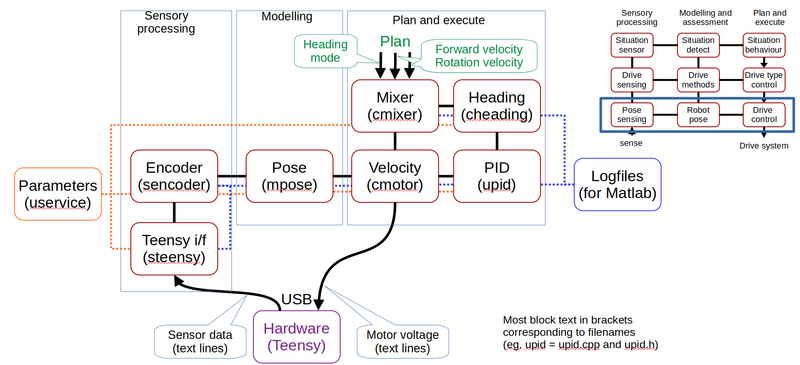
Figure 2. The lowest level in the control software. The encoder ticks are received form the hardware (from the Teensy microprocessor) in the sensor interface. The encoder values are then modeled into an odometry pose. The pose is used to control the wheel velocity using a PID controller. The desired wheel velocity for each wheel is generated in the mixer from a desired linear and rotational velocity.
Contents |
Hardware Teensy
The Teensy handles all the sensors connected to the microprocessor and the wheel motors as well as the up to 5 servos.
The sensor data is available as subscriptions with a constant sample rate. The sample can be specified in units of 1 ms. The USB connection has a bandwidth of about 4000 sensor messages per second.
All subscription requests start with the 'sub' keyword followed by the message key for the data type and the sample time in milliseconds, e.g:
sub svo 50
that subscribes to the servo status (for all 5 servos) every 50 ms. The Teensy interface will add the CRC and make sure it is received.
Teensy i/f
This is the Teensy interface controlling the USB interface to the Teensy.
Commands to the Teensy can be sent in two ways, trusted or best effort. The trusted commands await a confirmation from the Teensy; if this is not received within 30ms, it is resent - up to 3 times. If still not confirmed, the message is dropped (most likely, the connection is dead, or two applications are listening to the same USB device. The 'best effort' tye is sent once only; this is the fastest communication - like motor voltage in a control loop. If one message is lost, a similar value will be sent at the next sample time.
Both types are further secured by a simple CRC check.
All received messages are sent to the service module for decoding. All outgoing messages use the send method in this module.
All communication on the interface can be logged.
The module is coded in the steensy.h/steensy.cpp files.
The messages look like this - timestamped by the logging function.
% teensy communication to/from Teensy
% 1 	Time (sec) from system
% 2 	(Tx) Send to Teensy
%   	(Rx) Received from Teensy
%   	(Qu N) Put in queue to Teensy, now queue size N
% 3 	Message string queued, send or received
1687200276.5853 Tx ;75!setid robobot
1687200276.5853 Rx ;04hbt 47.9792 128 1581 4.64 0 7 74.1
1687200276.5866 Rx ;57# got new name (get with 'id')
1687200276.5867 Rx ;65confirm !setid robobot
1687200276.5869 Tx ;80!setidx 2
1687200276.5880 Rx ;70confirm !setidx 2
1687200276.5881 Tx ;47!idi
1687200276.5892 Rx ;37confirm !idi
1687200276.5893 Rx ;57dname robobot Sofia
1687200276.7838 Qu 1 ;01!sub enc 7
1687200276.7839 Qu 2 ;04!sub hbt 500
1687200276.7842 Qu 3 ;34!sub gyro0 12
1687200276.7842 Qu 4 ;78!sub acc0 12
1687200276.7842 Qu 5 ;37!gyrocal 0 0 0
1687200276.7842 Tx ;01!sub enc 7
1687200276.7853 Qu 6 ;81!sub svo 50
1687200276.7853 Rx ;90confirm !sub enc 7
The CRC is coded as two numeric characters that are the sum of all non-control characters in the message. The sum is reduced to two digits by a modulus 99 and 1 is added to avoid '00'. The two numbers are preceded by a semicolon ';'. Messages that need a confirmation are queued, and an '!' are added after the CRC code. The '!' is included in the CRC calculation.
Messages are coded as a character line in 7-bit ASCII, i.e., no Danish characters.
All messages are terminated by a 'new line', a '\n'.
Configuration options
In robot.ini, there are these options for the Teensy interface module:
[teensy]
device=/dev/ttyACM0
confirm_timeout = 0.04
log=true
print = false
The device is, in most cases /dev/ttyACM0, but it can be changed here.
The timeout unit is seconds; about 40ms is an OK compromise between detecting a failed communication and retransmitting too soon. Mostly a message is confirmed within 2ms.
Print is a debug feature to see all communication in the terminal window. Log is the same messages, but send to a file; this can be used for timing analysis of the communication or other debug issues.
Encoder
The encoder messages hold the encoder count for each wheel, e.g.
enc 4294967040 259 555 0
enc 4294967036 262 562 0
enc 4294967030 266 572 0
The first two numbers after the timestamp are the encoder count in a 32-bit integer format starting at zero at power up. The first number (left wheel) is here counting down and is thus close to the maximum value for a 32-bit unsigned integer.
The last number is debug values that will be removed at some point.
Configuration options
The streaming sample interval is set in the ini-file for the code, as
[encoder]
; encoder sample rate is also the sample rate for velocity control
rate_ms = 7       (unit is milliseconds)
log = true        (make logfile or not)
print = false     (print encoder values on console)
Samplerate is here set to 7 ms. Mostly a sample rate of 5 to 15 ms is OK. If much faster than 5ms, the reading of the incoming messages in the Teensy may get overloaded (late). Slower than 15 ms may be too slow for the control loop.
Pose
The pose is updated every time new encoder values are available.
The pose needs information about the drive-train and the distance between the driving wheels to calculate the pose from encoder values.
Configuration
The needed values are set in the ini-file:
[pose]
gear=18.0
; driving wheel diameter (m)
wheeldiameter=0.16
; encticksperrev: both flanks on both sensors are used, i.e. 16 magnets give 64 ticks
enctickperrev=64
; distance between driving wheels (m)
wheelbase=0.24
log=true
print = false
The gear is here 1:18 and the wheel diameter is 16 cm. The default motors have 16 magnets in the encoder disk, and as all flanks of the A and B signals are used, this gives 64 ticks per motor revolution.
Wheel velocity
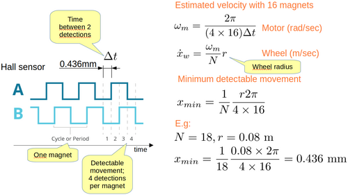
The wheel velocity for each wheel is calculated from the number of encoder ticks (de) time between encoder tick update (dt)
Figure 2. Wheel velocity calculation.
The distance traveled for the wheel between two encoder ticks is then:
distPerTick = wheelDiameter * pi / gear / encTickPerRev
With the values from the ini-file this gives distPerTick=0.436mm.
The velocity of the wheel is then calculated as
wheelVel = (de * distPerTick)/dt
where dt = time since the last update and de = encoder ticks since the last update
If no encoder ticks are detected in the sample time, then the velocity is estimated using the time since the last detected tick.
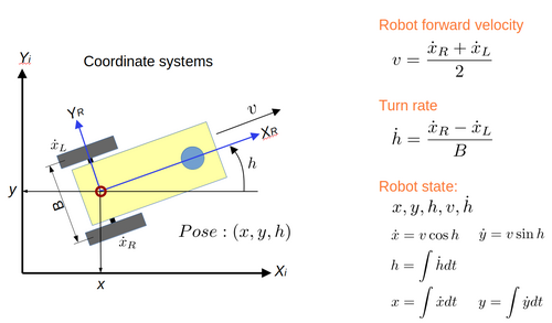
Robot velocity and turn rate
Figure 3. Definition of the used coordinate systems and how the pose is calculated from wheel velocity.


