Fejemis Teensy
Back to fejemis
Contents |
Drive Teensy
Block diagram with all interfaces and interface protocol should be here
USB Interface
The following list shows the result of sending the fejemis_drive a 'help' command (taken from the GUI when connected to the USB directly):
(Ru) : # ------ Commands available for drive -------
(Ru) : # 	veri and 'sub ver N' 	get version number and version string (and 'sub ver N')
(Ru) : # 	leave 	Stop all subscribed data - stop sending data
(Ru) : # 	help  	This help text.
(Ru) : # Sensor -------
(Ru) : # 	adci and 'sub adc N' 	Get raw ADC values (12V, current, IR1, IR2, motorV)
(Ru) : # 	inti and 'sub int N' 	Get number of interrupts for ADC1 and ADC2
(Ru) : # 	bati and 'sub bat N' 	Get battery voltage and current (volt [V], amp [A], lipo cells [N]
(Ru) : # 	timei and 'sub time N' 	Get timing info (cycle time[us], sense [us], +control[us], +logetc [us], adc cycle [us], adc cycles/control)
(Ru) : # 	ampi and 'sub amp N' 	Get current [A], ad4, ad5, adFactor, offset0, offset1
(Ru) : # Logger help -----------
(Ru) : # 	log XXX m 	Start control log every m ms (XXX = pose, time, usb, vel)
(Ru) : # 	log pose m 	Start pose control log every m ms (>= 1 ms)
(Ru) : # 	log get 	Get log (has=0/10 entries)
(Ru) : # 	log usb 	log USB io
(Ru) : # 	log stop 	Stop current log (no effect if log is full already)
(Ru) : # Drive control ------
(Ru) : # 	rc e v t 	Set control reference e=1:gamepad, e=2:run, v=velocity (m/s), t=turnrate rad/s
(Ru) : # 	fwl a 	Tell current front wheel angle (in degrees, 0 is forward, left is positive)
(Ru) : # 	confs B F 	Set steering configuration (B=wheelbase, F=dist to steering wheel [m])
(Ru) : # 	cvdrivei and 'sub cvdrive N' 	Get current control values
(Ru) : # 	cpdrivei and 'sub cpdrive N' 	Get control parameters. N = use,Kp,useI,taui,ilimit,1,useLeadf,tz,tp,useLeadb,tz,tp,usePre,tz,tp,useULim Ulim
(Ru) : # State settings -------
(Ru) : # 	setid N 	Set device ID to N (id=90, part of hbt) id=0 for factory settings.
(Ru) : # 	setname string 	Set device name to string (< 32 chars) should be 'drive'.
(Ru) : # 	stop 	Stop no control allowed until a start is received
(Ru) : # 	start	Allow control (default) rcSource=10 (-1=stopped)
(Ru) : # 	off T	Turn off power (cuts power after T seconds)
(Ru) : # 	on 	Power on (works only if not on battery)
(Ru) : # 	hbti and 'sub hbt N' 	Get time and state (heartbeat)
(Ru) : # 	idi and 'sub id N' 	Get device name and number
(Ru) : # IMU help -------
(Ru) : # 	gyroc 	Start gyro calibration (finished=1)
(Ru) : # 	magcal 	Set magnetometer calibration values (offset[3] rotate/scale[9])
(Ru) : # 	acccal 	Set accelerometer calibration values (offset[3] scale[3])
(Ru) : # 	acccal2 	make simple acceleration calibration with horizontal board
(Ru) : # 	gyroi and 'sub gyro N' 	Get current gyro value as 'gyro gx gy gz' (deg/s)
(Ru) : # 	gyrooi and 'sub gyroo N' 	Get gyro offset 'gyroo ox oy oz'
(Ru) : # 	acci and 'sub acc N' 	Get accelerometer values 'acc ax ay az' (m/s^2)
(Ru) : # 	accoi and 'sub acco N' 	Get accelerometer offset values 'acco xo yo zo' (m/s^2)
(Ru) : # 	magi and 'sub mag N' 	Get magnetometer values 'mag mx my mz' (uT)
(Ru) : # 	magwi and 'sub magw N' 	Get magnetometer raw values 'magw mx my mz' (uT)
(Ru) : # 	magoi and 'sub mago N' 	Get magnetometer offset values 'mago xo yo zo r11 r12 r13 r21 ... r33' (uT)
(Ru) : # 	imuposei and 'sub imupose N' 	Get IMU-based pose 'imupose roll pitch yaw (radians)
(Ru) : # Encoder help -------
(Ru) : # 	enc0 	Reset pose to (0,0,0)
(Ru) : # 	confw rl rr g t wb 	Set configuration (radius [m] gear [>=1] encTick [n/rev] wheelbase [m])
(Ru) : # 	enci and 'sub enc N' 	Get encoder value 'enc encoder interrupts' (integer)
(Ru) : # 	posei and 'sub pose N' 	Get current pose 'pose t x y h' (sec,m,m,rad)
(Ru) : # 	veli and 'sub vel N' 	Get velocity 'left right' (m/s)
(Ru) : # 	confi and 'sub conf N' 	Get robot conf (radius, radius, gear, pulsPerRev, wheelbase, sample-time)
(Ru) : # TOF distance help -------
(Ru) : # 	tofdi and 'sub tofd N' 	Get distance in meter from time of flight (TOF) sensor
(Ru) : # 	tof1i and 'sub tof1 N' 	Make TOF distance measurement
(Ru) : # HC-SR04 distance help -------
(Ru) : # 	hcsr 	Trigger new measurement
(Ru) : # 	sr04i and 'sub sr04 N' 	Get distance in meter from HC-SR04 sensor
(Ru) : # EE (configuration flash) --------
(Ru) : # 	eew 	save configuration to EE-Prom (flash)
(Ru) : # 	eer 	Read configuration from EE-Prom
The '(Ru) :' is added by the GUI - stands for: received from USB.
Turning control
The turning in the drive unit receives two messages:
- Linear velocity desired (v in m/sec) and turnrate w in radians/sec (RC message)
- Angle of front-wheel (in degrees) (fwl message)
The angle of the front wheel is used to calculate a turning radius d.
d = f/tan(theta) + B/2
where f is the distance to the bring wheel, theta is the angle of the front wheel and B is the drive base, the distance between the driving wheels.
The turn radius d is from the turning centre to the other wheel (the fastest wheel). The other wheel should have the desired velocity v2.
v2 = sqrt(v^2 + w^2)
with the sign from the linear velocity v. w is assumed to be in radians, and with the scale of the robot (B = 0.4m), it seems OK.
The inner wheel should then have a velocity v1 dependent on the turn radius d and the velocity of the other wheel v2
v1 = v2 - v2 * B / d
The sign of theta determines which wheel should have the higher velocity.
Front Teensy
Block diagram with all interfaces and interface protocol
(@todo)
Teensy Software structure
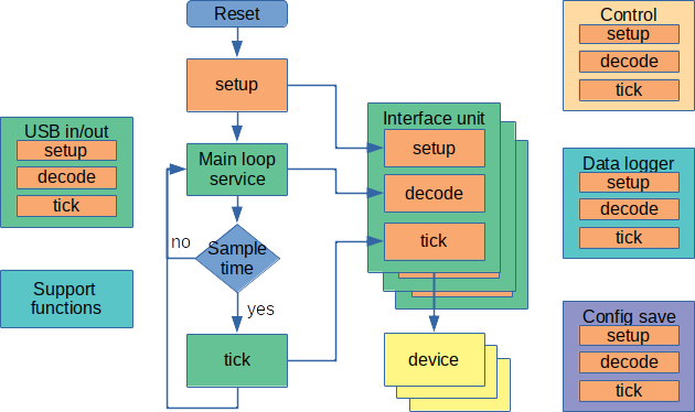
Figure: The Teensy software is structured with a main loop and a number of units. After reset all units are initialized in a setup function, after that the main loop is entered. The main loop services the USB and send commands to the units for decoding. At regular intervals, the sample clock tick, all units are called to execute any sample time function. Most units are interfaces to external devices such as IMU, motor drive or distance sensor. There is further support units for e.g. control.
Setup - loop overview
The setup and loop structure follows the Arduino sketch format. The file is a C++ file as the compilation is using a Makefile rather then the Arduino IDE.
The main file (main.cpp) code has this structure (shortened for clarity)
void setup()   // INITIALIZATION
{
 usb.setup();
 led.setup();
 imu.setup();
 enc.setup();
 sensor.setup();
 motor.setup();
 state.setup();
}
void loop(void)
{
 usb.send("# Starting main loop\n");
 while ( true )
 { // main loop
     usb.tick();     // incoming command service
   if ( startNewCycle ) // start of new control cycle
   { // mostly every 1ms
     imu.tick();     // for heading estimate
     sensor.tick();  // AD converter, e.g. battery maintenance
     irdist.tick();  // distance sensor
     enc.tick();     // wheel encoder and odometry
     state.tick();   // e.g. emergency stop
     control.tick(); // feedback control
     motor.tick();   // motor control
   }
 }
}
Unit structure
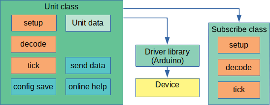
Figure: Each unit is coded in a separate file and has about the same structure. The unit is a class that holds the data from or to the device. The device is configured when the setup is called. The data from the device, or calculated from the data, is made available for subscription using a subscription class called USubss. The device is accessed using a standard Arduino-type library, for e.g. a I2C or an A/D interface. The unit may have configuration that need to be saved, e.g. calibration data or device mode that can be set from the interface, but needs to be saved.
Command decode
Commands from the USB connection is line oriented and consist of one line of text starting with a keyword. The line ends with a "new-line" (\n) or a combination if "carriage-return" (\r) and "new-line".
Request of data can be just the keyword, e.g.:
help   (for on-line help - list of available commands)
gyroi  (for one-time information about gyro measurement)
bati   (for one-time info about battery voltage)
or a keyword with parameters
ctrli vel (to get all the PID control parameters for velocity control)
Issue commands or send data, e.g.:
motv m1 m2  (to set motor 1 (left) and motor 2 (right) to a specified voltage.
rc e v t    (to do remote drive control with velocity "v" and turn-rate "t") "e" should be 2 for non-manual control.
Subscription
From the USB most data can be subscribed with the a line starting with the keyword "sub", e.g.:
sub gyro 10  (for subscription to gyro data every 10ms)
sub bat 200  (for subscription to battery status every 200ms)
The available subscriptions are generated in the "setup" part of the unit and holds also the on-line help text.
E.g. the wheel encoder unit has this subscription setup code (in enc.cpp):
void setup()
{
 ...
 addPublistItem("enc", "Get encoder value 'enc encoder interrupts' (integer)");
 addPublistItem("pose", "Get current pose 'pose t x y h' (sec,m,m,rad)");
 addPublistItem("vel", "Get velocity 'left right' (m/s)");
 addPublistItem("conf", "Get robot configuration (radius, radius, gear, pulsPerRev, wheelbase, sample-time)");
}
At tick-time subscriptions are serviced, and if it is time, the "sendData(item)" is called, e.g. for the wheel encoder unit:
void UEncoder::sendData(int item)
{
 if (item == 0)
   sendEncStatus();
 else if (item == 1)
   sendPose();
 else if (item == 2)
   sendVelocity();
 else if (item == 3)
   sendRobotConfig();
}
Configuration save
The Teensy has 4096 bytes of configuration flash memory, this is used to store settings and calibration values.
The use of this memory is controlled by the "config save" unit in the file "eeconfig.cpp".
The unit is controlled by two commands "eew" (save) and "eer" (load). On reset the configuration is loaded.
If the ID number is set to "0", all configurations are reset (to factory settings). To save any configuration, set ID number with the command "setid N" where N is a number > 0.
Configuration is saved as a stack, and each unit must therefore save and load exactly the same amount of data. Add load and save to the list in "eeconfig.cpp" when new units are added that need configuration saved.
The load and save are like e.g.:
void UImu::eePromSave()
{
 eeConfig.push32(offsetGyro[0]);
 eeConfig.push32(offsetGyro[1]);
 eeConfig.push32(offsetGyro[2]);
 // accelerometer
 for (int i = 0; i < 3; i++)
   eeConfig.pushFloat(accOffset[i]);
}
void UImu::eePromLoad()
{
 offsetGyro[0] = eeConfig.read32();
 offsetGyro[1] = eeConfig.read32();
 offsetGyro[2] = eeConfig.read32();
 gyroOffsetDone = true;
 //
 for (int i = 0; i < 3; i++)
   accOffset[i] = eeConfig.readFloat();
}
Update tick
The timing is based on a 10 us timer and the following is defined (in "main.cpp")
// control period is time between control calls
// and is in units of 10us, ie 125 is 1.25ms or 800Hz
#define CONTROL_PERIOD_10us 100
// sample time in seconds
#define SAMPLETIME  (0.00001 * CONTROL_PERIOD_10us)
The SAMPLETIME is a floating point number in seconds. The example above is for 1ms sample time.
All units tick() function is called at this interval. For new units the call must be added in the main code, like for the motor unit:
void UMotor::tick()
{ //
  implementMotorVoltage();
  // subscription
  subscribeTick();
}
It there is data subscription associated with this unit, then the subscribeTick() must be called to service the subscriptions.

