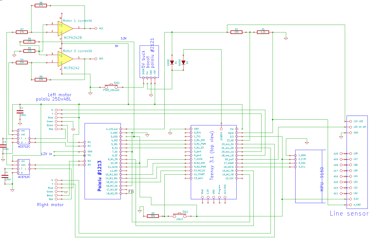
Schematic
From Rsewiki
RegBot schematic revision 2A
Teensy
The teensy USB-5V connection to Vin is cut on the teensy-board, to allow 5V-PSU to supply in all cases.
Schematic
Should be updated with version 2B.
 Figure is version 2A PCB (never used).
There is further allowed for additional interfaces (version 2B):
- Line sensor - blinking LEDs at 1kHz and 8 sensors - connected to 8 A/D converters on the Teensy.
- IR distance sensors (Sharp 2Y0A21F) two, that is connected to 5V and A0 (IR1) and A1 (IR2) on the processor.
- Interface to Nordic Radio board with SPI interface (not in software yet)
- Serial interface (Teensy pin 0 (RX1) and 1 (TX1) (not supported by software yet).
- Addition of power control IC, but this is pt. bypassed by a jumper.
Future improvements
Future improvements should replace the Pololu 5V switch mode supply by a 7805 linear controller, as the idle power consumption by the converter is higher than the Teensy 5V current. Yhis would allow the processor to go to sleep mode if battery volatge is getting low (this is implemented in software).
Some plugs (IR-sensor and Nordic radio) should be relocated, as they conflict with Teensy USB cable.
A battery ON/OFF switch should be mounted directly on the PCB.