Control
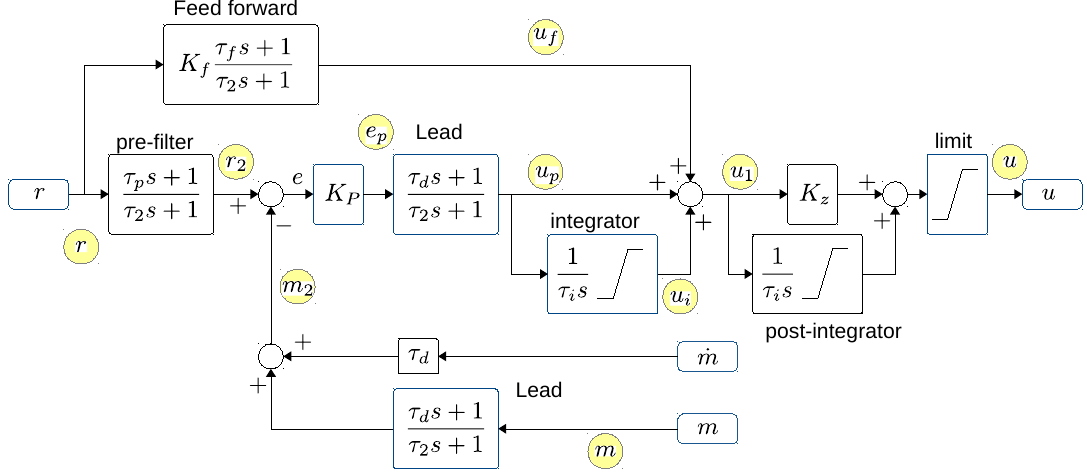
Figure 3. The general PID controller design with additional optional controller parts. "r" is reference input. And after the optional "pre-filter" the reference is compared with the measured value "m", optionally through a Lead filter. The "m-dot" is an optionally derivative of the measurement, that can be used for a less noisy Lead (with tau_d as normal, but no pole). The error signal "e" is fed through a gain "Kp", an optional Lead and an optional integrator. After this the output "u1" is summed from "up" (proportional/Lead), "ui" integrator term and "uf" from an optional feed forward branch. The output "u1" can further optionally be integrated (if Kz=0, if Kz=1 then the post-integrator has a zero). The output is finally limited to signal "u".
The yellow circles indicate the datapoints that can be logged.
All integrators can be limited. The integrators are further disabled if the output limiter limits the output. Some of the control interfaces (all but the balance controllers) further disables integrators when there is defined an acceleration limit in the mission, and this actually is limiting the acceleration.
The "post-integrator" is (mostly) usable in the balance controller.
The balance controller replaces the "Lead" after "m" with a "1", and uses tau_d after "m-dot", and "m-dot" is connected to tilt velocity from the gyro.
