Flexbot
Contents |
Introduction
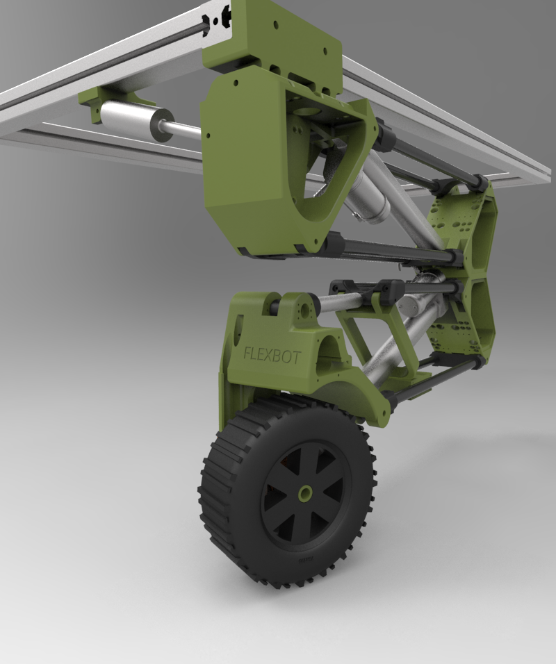
This is the main page of Flexbot. Here you will find all information and instructions related to the Flexbot project. A very important resource of this project is the git-repository which holds all documents, drawings, schematics and software.
Information
Documents, drawings and software (git repository)
Hardware design overview and open items (to-do).
Mechanical design modification to do list - design change request list (please amend when you note a problem / and delete when solved)
Software to do list - change request and to do (please amend when you note a problem / and delete when solved)
Flexbot parts list - PCB layout and part numbers.
Project plan notes
Instructions
MAVLink communication protocol
Updating, compiling and uploading Teensy code from the NUC
Current state of Flexbot
This section presents a very short summary of the current state of Flexbot. When a new change (of relevance i.e. no minors) is made, please update this section by adding a new line on top of the existing.
- 03/12 2017: One complete leg of Flexbot has been build. PCBs have been fabricated and mounted. Main PCB holds all I/O + Teensy, another distributes power and thirds are current sensing breakout boards. No design errors have been identified to this point. MAVLink have been implemented as communication protocol. A GUI have been designed to visualise data wirelessly from Flexbot and simple control means have been implemented to test all actuators on Flexbot.
- 23/07 2017: The mechanics from wheel to knee is finished. Electronics including external sensors have been mounted. Software supports basic functionality for interfacing, control, test and logging of each actuator (wheel, heading, height) and sensor.
Software terminal interface
This is deprecated and replaced with MAVLink + GUI as of 03/12-2017. However code still remains in source code - not active
Each Teensy can be interfaced separately via USB communication. Simply plug in a USB cable, open a serial communication in Putty, Arduino or whatever you prefer and type
help
This should return a menu with all options for the connected device. This should include:
- Changing controller and reference parameters
- Starting and stopping
- Printout of sensor data (to be used for debugging)
- Adding and removing items for logging
- Logging features (start logging, log interval and retrieve log in a MATLAB compatible format)
- Save and load to and from EEPROM (holds logging parameters and controller setting)
