Regbot calibration
(→Edge) |
(→Edge sensor calibration) |
||
| Line 67: | Line 67: | ||
The bars should be more than half filled and not saturated, and flickering slightly. | The bars should be more than half filled and not saturated, and flickering slightly. | ||
Now, press the "calibrate on white", then the new calibration values will be shown for all 8 sensors. | Now, press the "calibrate on white", then the new calibration values will be shown for all 8 sensors. | ||
| + | |||
Lift the robot, so that the sensor sees nothing and press "reflection on black". | Lift the robot, so that the sensor sees nothing and press "reflection on black". | ||
Revision as of 14:48, 24 May 2019
Contents |
Calibration
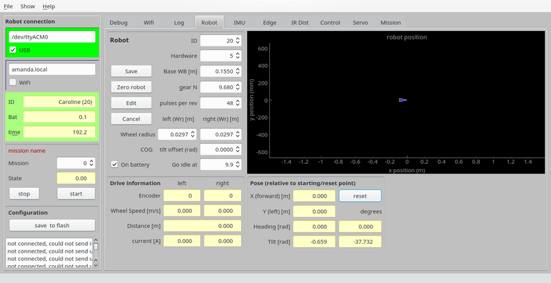
In the REGBOt GUI, the "robot" pane has the basic configuration
Figure 1. Basic robot settings.
- "Base WB [m]" is the distance between driving wheels. This is important for heading calculation and turning.
- "gear N" is gear reduction - normally 9.68
- "pulses per rev" is encoder configuration - number of pulses for one motor revolution - normally 48.
- "wheel radius" is important for distance calculation, and a bit for velocity and turning.
- "COG tilt offset" Center of Gravity tilt offset is important when keeping balance, should be adjusted, so that "tilt" (lower right) is 0, when in balance (hand held), if not, then add tilt value to "COG tilt offset". Accuracy should be about 0.01 radian (0.5 degree).
To change, press "edit", do the change and press "save" - and to be permanent after a reboot press "save to flash"
Gyro
The gyro is primarily used when in balance, but could be usefull for turning as well. The gyro has an offset, that can be calibrated away.
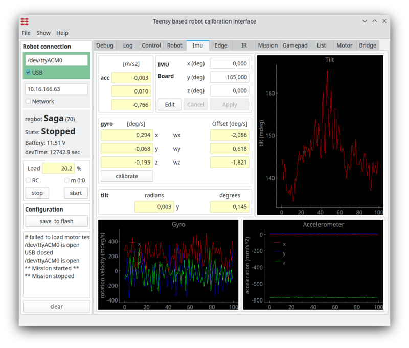
Figure 2. Gyro calibration. The lower left graph are the gyro values, when tha calibration values are implemented. The lower right graph is the accelerometer (raw) values - no calibration offered here. The top right graph is the tilt angle - a combination of gyro and acceleromerter values (complementary filter).
- To calibrate, make sure the robot is steady (no movement, no touch) then click the "calibrate" on the "IMU" pane. This will average the values over 1s and use as an offset.
- after this the 3 gyro values should have zero mean.
Encoder
Encoder calibration attempt to compensate for the uneven sized magnets in the magnetic encoder.
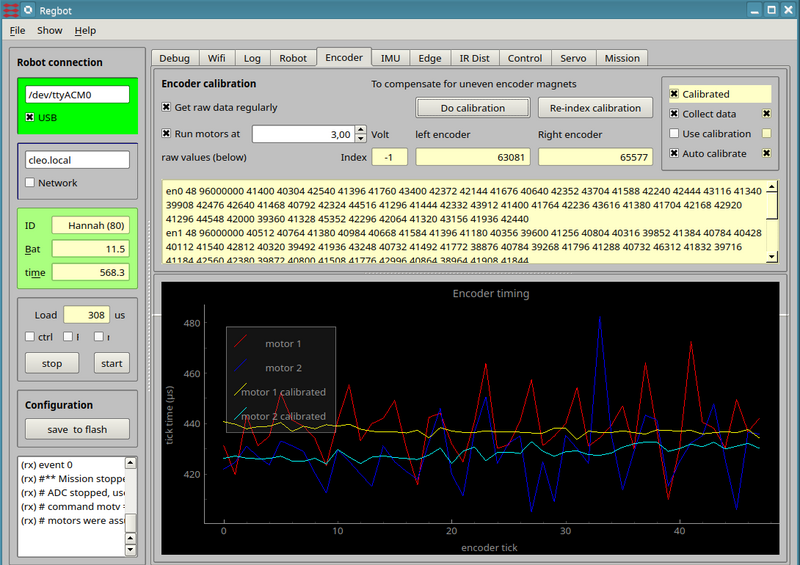
Figure 3. Calibration the encoder. The graph shows for all 48 encoder tics the time between the tics at constant velocity. Ideally it should be a straight line.
- To calibrate tick both "Get raw data regulary" and "Run motor at 3V" (wheels away from floor).
This will show some rather uneven lines in the plot.
- press the "Do calibration" button, once the velocity is stable.
This should make the calibrated lines more straight.
- Tick also the "Use calibration" (to the right) to use the calibrated values. If this is ticked and the calibration is out of sync, then it probably is worse than no calibration.
- NB! the calibration will only work as long as all encoder tics are counted, i.e. not after a reboot.
Edge
Edge (or line) detector for tape lines.
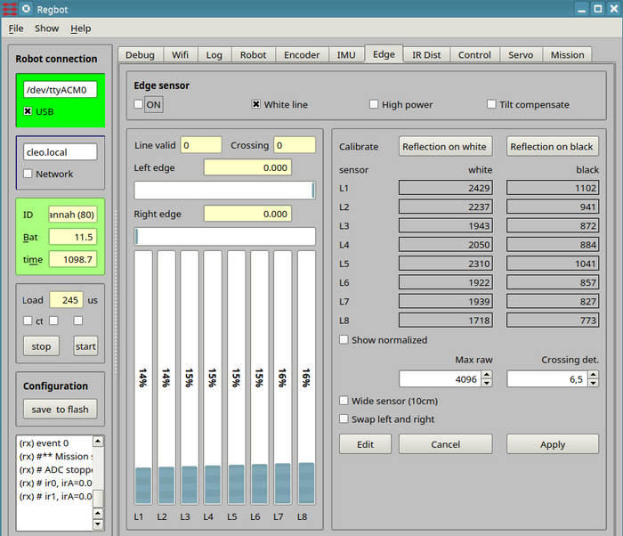
Figure 4. Calibration line sensor.
Turn on line sensor by ticking the "on" field.
Turn on
Select "White line" - system is never tested on a black line (may/2019).
High power and tilt compensate should only be used when regot is in balance.
To change, pres first the edit button, and when finished press the apply button (followed by the "save to flash" to make sure it stays after a reboot.
Edge sensor calibration
Place the robot so that the illuminated area is on the white part of the (tape) line, and the robot is in its normal configuration (i.e. all wheels on the ground).
The bars should be more than half filled and not saturated, and flickering slightly. Now, press the "calibrate on white", then the new calibration values will be shown for all 8 sensors.
Lift the robot, so that the sensor sees nothing and press "reflection on black".
Again press "apply" and "save to flash" to save.
Crossing detect
The crossing detect (Crossing det.) value is a value for how many and how much of the sensors sees an area with high reflection.
IR distance
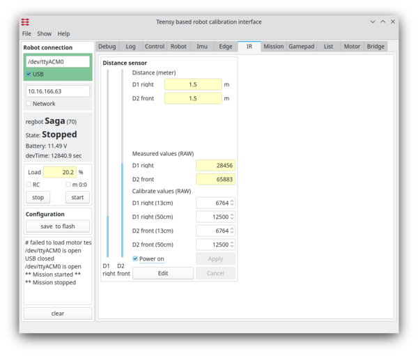
The 2 distance sensors need calibration too.
Figure 5. Calibration of the IR sensor.
