AruCo Markers
Contents |
ArUco functions and camera calibration overview

The ArUco functions in the camera class are meant as an inspiration, to give a starting point to people, who want to use the OpenCv ArUco library.
The ArUcu module from the OpenCv library is used to detect the markers. The library can be downloaded on this website, where there also is some information about the functions from the library.
The objective of the implementation of the functions from the OpenCv library is to detect markers on a 3D printed block. The block has 6 ArUco markers on it. One on each side. The markers are placed in the following way:
top: 30, bottom: 31, front: 33, back: 34, right: 35, left: 36
The functions are only tested with this specific block, but it should also work with other markers if the last digit in their ID corresponds to those on the blocks. eg the numbers {50, 51, 53, 54, 55, 56}
Settings
Some of the settings are dependable of the printed ArUcu markers and the hardware (camera) used to detect. So the first thing to do, when starting a new project is to check and if necessary update this parameter.
markerDictionary
The DICT_4X4_100 predefined dictionary is used in this code. DICT_4X4_100 means that the marker is a grid of 4 by 4 black or white squares and valid marker Id are from 0 to 99. Change the variable markerDictionary if it desired to be able to detect other markers.
arucoSqaureDimentions
The physical size of the markers influences the scale of the translation vector. In this setup, the markers with Id 30 and 31 are 10 cm the other 4 markers are 2 cm. A variable arucoSqaureDimentionsSmall is used to scale the vector if it has detected a small marker Change the arucoSqaureDimentions and/or arucoSqaureDimentionsSmall, if it is desired to detect markers of other sizes.
cameraMatrix and distanceCoefficients
To estimate the position of the markers is a camera matrix and distance coefficients needed. The file "ILoveCameraCalibration" contains these variables. At the beginning of the program is the variable loaded from the file. The camera matrix and distance coefficients can also be obtained by running the camera calibration process. The camera calibration process changes the variables in the file. It is recommended to run the camera calibration process, to be sure that the values in the file not have been obtained on another robot. Go to the AruCo_Markers#Camera_Calibration section for more details on camera calibration.
How to use the functions from the umission
When a new detection of AcUco markers is wanted, simply call the function:
cam->startWebcamMonitoring();
The function takes a picture and runs through all the AruCo functions. The results are saved in an array of structs called arUcoVal. The values are directly accessible from umission. For example, can the distance to the AruCo marker 30, be accessed in the following way:
cam->arUcoVal[30].disteance2marker;
The struct ArUcoVal contains the values related to one ArUco marker
- markerId is the ID of the marker ectracted from the vector markerIds found by the cv::aruco::detectMarkers function
- frame is the picture where the markers are detected.
- rVec and tVec are also found by cv::aruco::detectMarkers.
- label is a sting printet on the picture with rVec, tVec ect.
- robotTurnCommand is a string that can be send to the robot, so that it turn and is positioned parallel to a on of the markers axes
- robotDriveCommand drives the robot the marker
- rob_Ar_H is the homogeneous transformation and rotation matrix that transform a point in the marker frame to a point in the robot frame.
- done indicate that the robotTurnCommand has been found
- markerUnitVecX, markerUnitVecY, markerUnitVecCaliperZ; is the unitvectors of the marker represented in the robot frame
- disteance2marker id the distance from the robot to the marker in meters
- angle2markerX and angle2markerY are the angle between the robot and the x or y axis of the marker frame respectively */
Rotation and Translation
The function estimatePoseSingleMarkers calculates a rotation vector.
rVec=[a b c]
The rotation vector is a compact notation of the Rodrigues notation. The Rodrigues notation notates a 3D rotation by rotation axis v and an angle θ. The object is rotated around v with the angle θ. The compact notation uses only 3 values to represent the rotation.
θ = sqrt(a²+b²+c²)
and
v = [a/θ b/θ c/θ]
The Rodrigues function from the OpenCv library is used to convert the compact Rodrigues notation to a rotation matrix.
This rotation matrix together with the translation vector forms a homogeneous transformation and rotation matrix ArcamH. When a point ArP in the marker coordinates system is post multiplied on this matrix ArcamH, will the result be the point in 3d coordinate system of the camera. A similar transformation matrix camrobH transform coordinate from camera to robot coordinate system. Together
ArrobH = camrobH x ArcamH
is formed. ArRobH transform vectors from marker coordinate to robot coordinate system.
Camera Calibration
The Ucamera class also include functions to find the camera matrix, by using a checkerboard to calibrate the camera. follow the following procedure to calibrate the camera:
- Measure the size of a single square on the checkerboard and update chessboardDimensions. (Be as accurate as possible and use a Caliper)
- Count the number of squares in each row and column and subtract 1. And update chessboardDimensions.
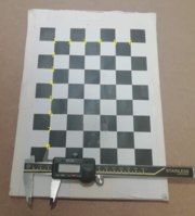 Checkerboard with dimensions (6,8) marked
- Then uncomment the function cameraCalibrationProcess(cameraMatrix, distanceCoefficients);
- Run the program.
- Position the checkerboard in front of the camera and confirm by looking at the screen that it has been detected.
- Press space to save the frame (in the image window, not the terminal).
- Move the checkerboard to a new position and repeat from step 5.
- When more than 15 frames have been saved the Enter button can be pushed to calibrate. 15 is the minimum frames the code will accept, but it is advisable to take 20+. The more frames the better result.
- When the terminal writes “calibrated and saved", exit the calibration by pressing ESC.
- The cameraMatrix and the distanceCoefficients are saved to a file called ILoveCameraCalibration. The function loadCameraCalibration loads the values from the file. The function loadCameraCalibration is called by the UCamera constructor

Last updated by --S130067 (talk) 18:13, 26 August 2019 (CEST)