Fejemis battery control
Back to fejemis
Introduction
The battery system is 24V, but split into 2x11.1V Lip batteries.
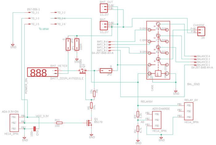
Each battery has a charger and a charge control board as shown in the schematic below.
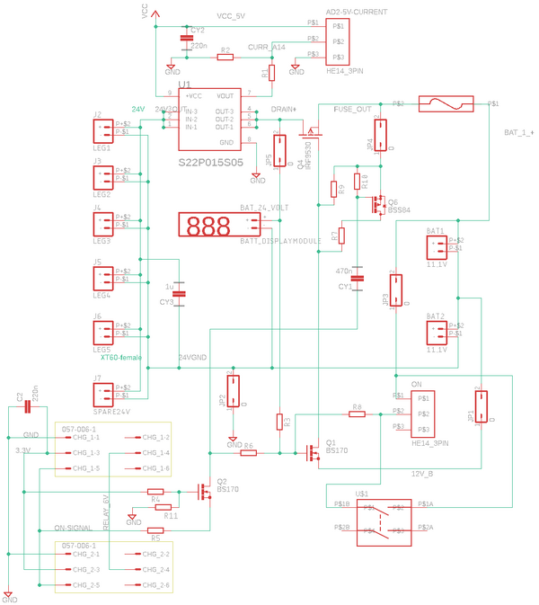
Another board combines the two batteries and has a number of XT60 plugs for power distribution as shown below.
Charger board
Battery charge board: The battery is connected (with an XT60) at top-center called 'BAT' with the balancing cable at the pins just below. The charger is connected to the left (again XT60 and balance plug), The charge is disconnected using a relay, when not in use. The relay is activated with a small 6V supply from 230V mains (RELAY_6V). The battery meter is connected when power is on using Q3 and Q1. The AD3-CHARGE (lower-right) is for the u-processor to detect that we are charging.
Power distribution board
The power distribution board has 6 XT60 output plugs (left). The two battery charge boards are connected in the right-centre position. A fuse and Q4 transfer the battery voltage to the output plugs. The U1 block is a current sensor. The on-switch is in the lower-right corner. Q2 allows the processor to turn off the power by lowering the ON-SIGNAL on the source of Q2, the drain of Q2 will then also go low, turning off Q1. The gate of the power FET Q4 then slowly goes high, and the power is off. The Q6 makes the transition faster by discharging the gate capacity of Q4, with a Q6 gate signal through the CY1 capacitor.

