Python interface
Contents |
Qt GUI interface design
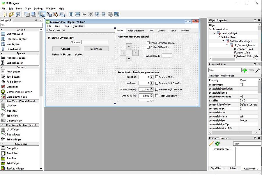
The Regbot desktop application is designed using the Qt-Designer app which uses the widgets from the Qt GUI framework. The application gives a possibility to quickly build interfaces using the drag-and-drop feature for placing necessary components in your interface. The framework provides the developer with the most common user-interface objects, however, it might be lacking some of the objects that other frameworks support, like basic shapes.
This user interface was designed using Python 3.7.9 and Qt version 5.
Note*To some extent, it was possible to use Visual Studio, but I ran into some problems with finding the necessary libraries for some tasks I wanted to use (like cv2, keyboard and some PyQT libraries). A Safe choice was to use one Python development platform on your PC, for example, Spyder (as it was necessary to use this for other courses).
At first, to use Qt-Designer version 5 with python it is necessary to install the necessary python packages:
# Installing PyQt5 package
pip install pyqt5-tools
pip install pyqt5
When your user-interface is finished and is saved as .ui file from The Qt designer, the file is ready to be translated to C++ or Python interface code. The .ui file will be converted to .py file with all the parameters that were set in Qt-Designer app like - object name, size, and many other parameters that correspond to each specific object.
After installing and designing your user-interface it is necessary to convert your user interface .ui file to a .py file, that can be run in your program. The translated .ui files can be auto-generated using the following commands:
# Generating Python interface file from Qt-Designer .ui file
pyuic5 -x "filename".ui -o "filename".py
Note *This file is generated in the directory where the terminal was opened, so make sure that you know where this file is located after using this command.
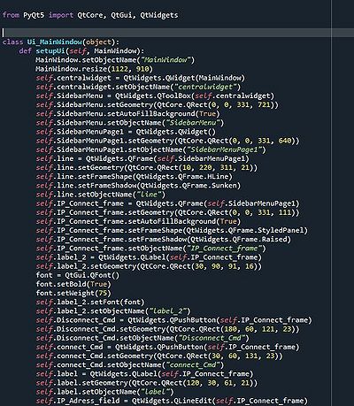
In the picture below, you can see an example of an auto-generated python interface file, that can later be included in the rest of your application as a user interface. By editing the object by the name, the actual user interface now can also be tweaked by editing the Python code, but this usually requires a more in-depth experience and knowledge of how Python user-interface code works.
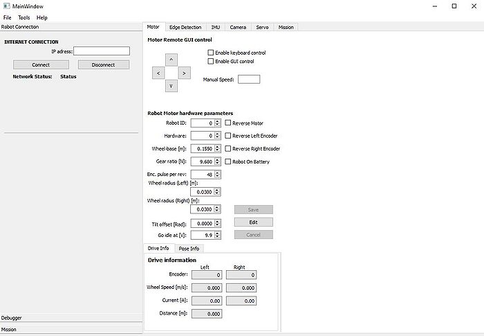
If this auto-generated python file is run on its own, the user interface is executed as an output of this program. Its objects don't have any functionality, because the actions have not been programmed yet for them.
To add functionality to the object of the user interface (like buttons, checkboxes, text fields, etc.), we can attach a function to the interface object to be executed, for example, if the check box is checked, or button is pressed. This can be done by taking the user interface object in the python .py file and passing your function to it as an argument.
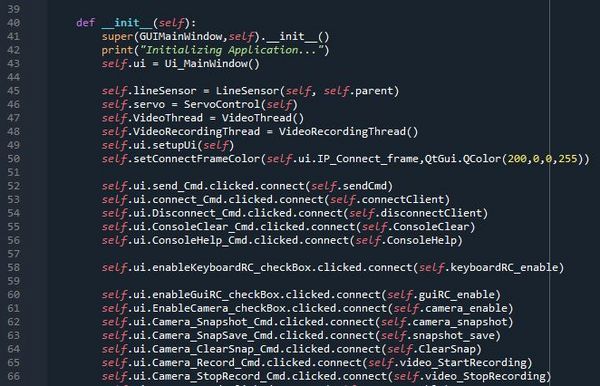
By running the python class script, the first function that is run is "__init__". In "__init__" usually we define all other python classes that need to be initialized and defined. We sort of define/initialize the functions that are going to be used in the program.
The following code is a template example of how to connect the user-interface object with the function in your program. The specific object-related function (clicked, released, pressed) varies from object to object.
# self."user-interface-file"."object-name"."function".connect(self."function name")
See the example below:
Programming GUI
As the whole Regbot firmware and bridge software is already programmed (see section "Navigation box software" on the main robobot page). And accessing the local@IP port 24001 we are able to receive and send byte-type messages to the network socket. Thus, by building a GUI, it is possible to control the robot remotely, read/test sensor values, read and write robot system parameters to its configuration just by reading and sending byte-type network messages from/to the IP adress port.
The first thing that is needed to do is install the socket library and define/initialize is the network socket (internet connection) to the robobot bridge.
$ pip install sockets
# import socket
  class GUIMainWindow(QtWidgets.QMainWindow):
       socket = socket.socket()
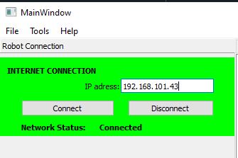
When that is done, we connect the actual "connect" button to the connectClient() function do all the necessary steps to establish a connection with the chosen IP address. The Connect client function connected with the button action when "clicked".
self.ui.connect_Cmd.clicked.connect(self.connectClient)
The connectClient() function implementation can be seen below. To make a stable socket connection, at first, it is required to get the address information parameters like - Adress Family, Socket Type, and the Adress Info (IP and port). Then using the previously extracted parameters we define the actual network socket and connect with the IP address using socket.socket.connect(IP). If the attempt to make a connection is faulted, it is necessary to close a connection using socket.close() function. In the code below some extra functions are implemented as well, for example, to change the frame color or text in the status label to indicate that the connection has successfully been made or not.
 def connectClient(self):
       if not self.wifiConnected:
           IP = str('192.168.43.101') # Connect automatically to this address
           #IP = str(self.ui.IP_Adress_field.text()) # Manual IP adress input
           # Getting address info for the connection
           for addressInfo in socket.getaddrinfo(IP, 24001, socket.AF_UNSPEC, socket.SOCK_STREAM):
               print("Socket Info " + str(addressInfo)) # Printing the whole adress info
               AddresFamily = addressInfo[0] # Extracting the Adress Family type
               print("# Adress Family ", AddresFamily)
               SocketType = addressInfo[1] # Extracting the Socket Type
               print("# Socket Type " , SocketType)
               IP = addressInfo[4] # both IP and port number
               print("# IP adress and port ", IP)
           try:
               self.socket = socket.socket(AddresFamily, SocketType, 0) # Making a actual networ socket with necessary adress parameters.
               self.socket.settimeout(5)
           except OSError as msg:
               print("# Network Connection timeout - retry")
           try:
               self.ConsoleMessage += "Connecting to Client..."
               self.ConsoleMessagePush = True
               print("Connecting to Client...")
               self.socket.connect(IP) # Connecting to the adress
               self.wifiConnected = True
               self.setConnectFrameColor(self.ui.IP_Connect_frame,QtGui.QColor(0,255,0,255))
               self.ui.IP_NetworkStatus_label.setText('Connected')
               print("Connected")
               self.ConsoleMessage += "Network is Connected\n"
               self.ConsoleMessage += "Socket Info " + str(addressInfo) + "\n"
               self.ConsoleMessagePush = True
           except OSError as msg:
               self.socket.close() # closing the connection if faulted
               self.ui.IP_NetworkStatus_label.setText('Faulted')
Note *To avoid the confusion, why the connection with the Raspberry Pi suddenly faulted, it is required to continuously send "alive" or heartbeat command"u5". The Pi is configured in a way, if it doesn't receive anything in the connection socket for couple of seconds, the connection is terminated.
In a similar fashion the Disconnect button in the GUI is connected with the disconnectClient() function. To correctly close down the connection, it is required to shut down the socket using socket.shutdow() and then close the connection using socket.close(). As one can notice, other different functions are called in disconnectClient() function, which stops other features in the programm.
 def disconnectClient(self):
       if self.wifiConnected:
           print("Disconnecting...")
           self.ui.IP_NetworkStatus_label.setText('Disconnecting')
           self.wifiConnected = False
           self.video_StopRecording()
           self.socket.shutdown(2) # Shutting down the socket
           self.socket.close() # Closing down the connection
           self.setConnectFrameColor(self.ui.IP_Connect_frame,QtGui.QColor(200,0,0,255))
           self.ui.IP_NetworkStatus_label.setText('Disconnected')
           print("Disconnected")
           self.ConsoleMessage += "Network is Disconnected\n"
           self.ConsoleMessagePush = True
The messages in the code to the socket can be written using the socket function socket.send("MESSAGE-TEXT"). The most important thing that the string message has to be converted to a type byte to be able to successfully send the message to the socket.
 def connectionWrite(self,MESSAGE):
       MESSAGE = bytes(MESSAGE, 'utf-8')
       if self.wifiConnected:
           self.socket.send(MESSAGE)
       if (self.wifiConnected):
           if (self.ui.TX_checkBox.isChecked()):
               self.ConsoleMessage += "(tx)->"+ str(MESSAGE) +'\n'
               self.ConsoleMessagePush = True
       else:
           self.ConsoleMessage += "Network not connected, could not send message -" + str(MESSAGE)
       pass
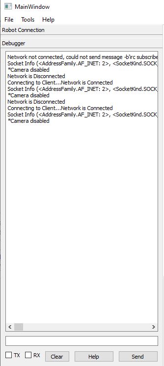
Here is visible the screenshot of the debugging message window in the GUI. Here using TX and RX checkboxes we can see what messages are sent to the connection and received back. As described before, the GUI button "Send" is connected with the text input field and function connectionWrite(). By pressing the Help button, the "help" message is sent to the socket, and then as the reply, we are receiving back the reply from the connection. This reply consists of a list of function messages that can be written in the socket in order to receive actual data from the robobot bridge.
By sending the specific predifined command to the socket, the reply will be provided that later can be used as an actual value for editing the robot configuration, displaying the sensor values etc. However, the reply is sent in a form one string, so the decoding function is needed to be implemented to seperate the values. The list of these messages can be seen here:
(rx)-> # help for special second parameter:
(rx)-> #   get          Gets the value of the tata item
(rx)-> #   meta         Gets 'key meta r vs s p description': r=responder, vs: 0=val 1=seq, s=source, p=priority
(rx)-> #   subscribe p  Set subscription priority 0=none, 1=fast (10ms), 5 = slow (6sec), 6=all updates
(rx)-> #   status       Sends status 'key status c T n p p p p ...' c: update count, T: since last (sec), n=clients slots, p client priority
(rx)-> #   name xxx     Sets name or description for data item
(rx)-> #   logopen      Opens a (new) logfile and log all updates with timestamp (key.txt)
(rx)-> #   logclose     Closes logfile (if open)
(rx)-> #   h            This help
(rx)->
(rx)-> # NB! you now subscribed to all '#' messages
(rx)-> # (use 'robot silent' or '# subscribe 0' to undo)
(rx)-> # Robot connection has these subcommand options:
(rx)-> #     clogopen   open communication log for all traffic to and from Regbot
(rx)-> #     clogclose  close these logfiles
(rx)-> #     help       This help text
(rx)-> #     Regbot communication open=1
(rx)-> # RegBot commands ($Id: command.cpp 1175 2020-01-04 15:40:53Z jcan $)
(rx)-> # M=N         Select mission 0=user mission, 1.. = hard coded mission (M=0)
(rx)-> # i=1         Interactive: 0: GUI info, 1: use local echo of all commands, -1:no info  (i=0)
(rx)-> # s=N A       Log interval in milliseconds (s=5) and allow A=1 (is 1)
(rx)-> # lcl 0 0 0 0 0 0 0 0 0  Log control: vel,head,pos,edge,walldist,fwd-dist,bal,bal-vel,bal-pos (is 100000000)
(rx)-> # log start    Start logging to 70kB RAM (is=0, logged 0/1458 lines)
(rx)-> # log get      Transfer log to USB (active=0)
(rx)-> # motw m1 m2   Set motor PWM -1024..1024 (is=0 0)
(rx)-> # motv m1 m2   Set motor voltage -6.0 .. 6.0 (is=0.00 0.00)
(rx)-> # mote m1 m2   Set motor enable (left right) (is=0 0)
(rx)-> # u0..u8       Status: u0:ver,u1:measure,u2:mission, u3:log,u4:robot,u5:heartbeat,u6:mag,u8:motorVA
(rx)-> # u9..u14      Status: Line sensor u9=limit w, u10=limits B, u11=value, u12=raw, u13=pos and x, u14=ADC
(rx)-> # u15..u24     Status:  15=acc, 16=gyro, 17=gyro offs, 18=motor (A), 19=enc, 20=vel(m/s), 21=pos(m), 22=pose, 23=button, 24=voltage (V)
(rx)-> # u25..u31     Status:  25,26 encoder calibrate raw values (cpu clock units), u27,28 calibrate factors, u29 enc status, u30 line sensor, u31 line sensor gain
(rx)-> # v0..2        Status: v0:IR sensor data, v1:wifi status, v2 wifi clients
(rx)-> # xID          Get Control params, ID: cvel=wheel vel, ctrn=turn, cwve=wall vel, cwth=wall turn, cpos=position,
(rx)-> # cedg=edge, cbal=balance, cbav=bal vel, ctrl=rate limit
(rx)-> # ID x x ...   Set controler parameters (ID use Kp ... see format below)
(rx)-> # format: ID use kp iuse itau ilim Lfuse LfNum LfDen Lbuse LbNum LbDen preUse preNum preDen
(rx)-> # preIuse preItau preIlim ffUse ffKp ffFuse ffFnum ffFden LimUse Lim
(rx)-> # rid=d d d d d d d d d d  Robot ID set: ID wheelBase gear PPR RadLeft RadRight balanceOffset flags batt_low HW_version
(rx)-> # eew          Save configuration to EE-Prom
(rx)-> # eeW          Get configuration as string
(rx)-> # eer          Read configuration from EE-Prom
(rx)-> # eeR=X        Read config and mission from hard coded set X=0: empty, X=1 follow wall
(rx)-> # sub s p m    Subscribe s=1, unsubscribe s=0, p=priority 0 (high) .. 4(low), m=msg:0=hbt, 1=pose,2=IR,3=edge,4=acc,5=gyro,6=current,7=vel,8=mission
(rx)-> # sut t p      msg interval for priority, t=time in ms 1.., p=priority 0..4 (is 0=1 1=5 2=25 3=125 4=625)
(rx)-> # posec        Reset pose and position
(rx)-> # gyroo        Make gyro offset calibration
(rx)-> # mem          Some memory usage info
(rx)-> # start        start mission now
(rx)-> # stop         terminate mission now
(rx)-> # rc=A V T [B] Remote control A=0/1 (is 0), V=m/s (is 0), T=vel difference (is 0), B=1 try keep balance
(rx)-> # <add user-mission-line>     add a user mission line (3 lines loaded in 1 threads)
(rx)-> # <mod T L user-mission-line  Modify line L in thread T to new user-mission-line
(rx)-> # <clear>      Clear all user mission lines
(rx)-> # <get>        Get all user mission lines
(rx)-> # <event=X>    Make an event number X (from 0 to 31)
(rx)-> # <token>      Get all user mission lines as tokens
(rx)-> # :xxxx        Send data (AT commands) to wifi board (all except the ':') \r\n is added
(rx)-> # link=L,data  Send data to socket link L
(rx)-> # wifi use port SSID PW   Wifi setup (e.g. 'wifi 1 24001 "device" ""')
(rx)-> # wifi e/n     Echo all received from 8266 to USB link
(rx)-> # halt         Turn 12V power off (on by halt=0) (is 0)
(rx)-> # alive        Alive command - reply: <alive last="0.0xxx"/>
(rx)-> # iron 1       IR sensor on (1 = on, 0 = off) is=0
(rx)-> # irc 2 8 2 8 u i  IR set 20cm 80cm 20cm 80cm on installed
(rx)-> # servo N P V  Set servo N=1..3 (4,5) P (position):-512..+512 (>1024 = disable), V (velocity): 0=full, 1..10 P-values/per ms
(rx)-> # (status: (servo 1,2,3) enabled 0,0,0, P= 0, 0, 0, V= 2, 2, 2)
(rx)-> # servo -1 frw Set PWM frequency
(rx)-> # svo          Get servo status (same format as below)
(rx)-> # svo s1 p1 v1 s2 p2 v2 s3 p3 v3 s4 p4 v4 s5 p5 v5  Set servo status sx=enable px=position (-1000..1000), vx velocity 0 (full) 1..10 (slower)
(rx)-> # encc, enci     Encoder calibrate: enc: calibrate now, eni: Find calibration index now
(rx)-> # eneX=1       enec=1/0 enable timing collect, eneu=1/0 use calibration, enea=1/0 auto calibrate
(rx)-> # silent=1     Should USB be silent, if no communication (1=auto silent)
(rx)-> # help         This help text.
(rx)-> # ADC use=1, seq=0, resetcnt=0, reset
Receiving, Decoding and Translating received messages
When the correct message is sent, and the bridge has understood the message, it provides a reply. The reply usually is in the form as show in the following string - "keyword parameter1 parameter2 parameter3 ... parameter_n". For example, sending the message "u5", we receive :
(rx)-> hbt 6542.6 11.5319 0 0 0 221
where [0] element - is the keyword
[1] element - regbot time since startup
[2] element - battery voltage
[3] element - control active flag
[4] element - mission state
[5] element - remote control flag
[6] element - cpu load
The translation and the meaning of each element can be found in the previous "help" section right above this section.
It is possible to get a continuous stream of data of the selected parameter by sending a subscription command - "keyword subscribe x", where x is the priority of the subscribtion stream. When the subscription has been made, the Pi will provide a continuous stream of replies for the subscribed parameter.
For example sending a subscribrion command to subscribe to linesensor values:
liv subscribe 6
(rx)-> liv 3035 3279 3067 3178 3322 2683 3045 2761
*RAW values of the line sensor
To decode the received message, it is necessary to create a function that separates the values of the received string. Using the readReply() function, firstly make sure that we have a valid, stable connection and then with socket.recv(1).decode() we read the reply from the socket chatacter-by-character and putting them all together to get a string message. When the full message has been stacked together, we pass the "message" in the function decodeCommand() which will seperate the necessary values.
    def readReply(self):
       c = '\0'
       self.socket.settimeout(1)
       while (not self.stop.is_set()):
           if self.wifiConnected:
               n = 0
               if (c == '\n'):
                   MESSAGE = ""
               c = '\0'
               try:
                     while (c != '\n' and self.wifiConnected):
                           c = self.socket.recv(1).decode()
                           if (len(c) > 0):
                                   if (c >= ' ' or c == '\n'):
                                       MESSAGE = MESSAGE + str(c)
                     n = len(MESSAGE)
               except:
                     time.sleep(0.01)
               if (n > 0):
                   self.decodeCommand(MESSAGE, n)
           else:
                 time.sleep(0.1)
       pass
The "message" then is passed around, until it reaches the function that recognizes the initial keyword. *The Function also is printed on the GUI message terminal. For example, if the decodeCommand() function recognizes that the message belongs to linesensor.readData(), the message is treated further in this function.
   def decodeCommand(self, MESSAGE, n):
       if n > 0:
           if (self.ui.RX_checkBox.isChecked()):
               self.ConsoleMessage += "(rx)-> " + str(MESSAGE)
               self.ConsoleMessagePush = True
       if n > 1:
           gg = MESSAGE.split()

           if gg[0] == "hbt":
               print(gg, 'hbt')
           elif self.info.readData(gg):
               pass
           elif self.lineSensor.readData(gg): <------------------
               pass
           elif self.servo.readData(gg):
               pass
           if self.irdist.readData(gg):
               pass
As we received the message that belongs to linesensor.readData() function, we are able to split the array of string parameters and assign them to our own variables, that we can pass to our GUI objects.
# readData function from linesensor class
def readData(self, MESSAGE):
       used = True
       try:
           if MESSAGE[0] == "liv":
               self.dataReadLiv = True
               if self.ui.ls_show_normalized.isChecked():
                   maxraw = self.ui.line_disp_max_value.value()
                   self.lineValue[0] = maxraw * (int(MESSAGE[1],0) - self.lineMaxBlack[0])/(self.lineMaxWhite[0] - self.lineMaxBlack[0])
                   self.lineValue[1] = maxraw * (int(MESSAGE[2],0) - self.lineMaxBlack[1])/(self.lineMaxWhite[1] - self.lineMaxBlack[1])
                   self.lineValue[2] = maxraw * (int(MESSAGE[3],0) - self.lineMaxBlack[2])/(self.lineMaxWhite[2] - self.lineMaxBlack[2])
                   self.lineValue[3] = maxraw * (int(MESSAGE[4],0) - self.lineMaxBlack[3])/(self.lineMaxWhite[3] - self.lineMaxBlack[3])
                   self.lineValue[4] = maxraw * (int(MESSAGE[5],0) - self.lineMaxBlack[4])/(self.lineMaxWhite[4] - self.lineMaxBlack[4])
                   self.lineValue[5] = maxraw * (int(MESSAGE[6],0) - self.lineMaxBlack[5])/(self.lineMaxWhite[5] - self.lineMaxBlack[5])
                   self.lineValue[6] = maxraw * (int(MESSAGE[7],0) - self.lineMaxBlack[6])/(self.lineMaxWhite[6] - self.lineMaxBlack[6])
                   self.lineValue[7] = maxraw * (int(MESSAGE[8],0) - self.lineMaxBlack[7])/(self.lineMaxWhite[7] - self.lineMaxBlack[7])
               else:
                   self.lineValue[0] = int(MESSAGE[1],0)
                   self.lineValue[1] = int(MESSAGE[2],0)
                   self.lineValue[2] = int(MESSAGE[3],0)
                   self.lineValue[3] = int(MESSAGE[4],0)
                   self.lineValue[4] = int(MESSAGE[5],0)
                   self.lineValue[5] = int(MESSAGE[6],0)
                   self.lineValue[6] = int(MESSAGE[7],0)
                   self.lineValue[7] = int(MESSAGE[8],0)
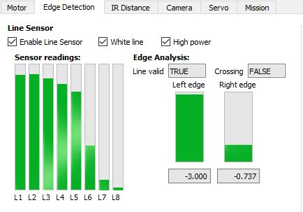
These values can be stored and assigned to line sensor GUI object element for displaying its value. By subscribing to different parameters like - liv,lib lip, we can get the calibrated values and configuration parameters for edge detection, crossing detection etc.
Manual Robot Control from the GUI
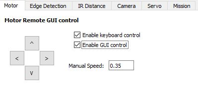
Just like it is possible to start the robot mission and control it remotely from the game-controller, it is possible to manually control the motor movement remotely from the user-interface or computer keyboard. As it can be seen in the picture below, the two checkboxes correspond to each mode - GUI control, where pressing the arrow buttons in the user-interface, will control the robot with the speed specified in the text-field.
Similarly, the robot can be controlled using the computer keyboard arrows, with keyboard control enabled and manual speed specified in the manual speed text-field.
Note *If the manual speed is not specified, the remote control is not possible.
The function that controls the remote manual control from the computer keyboard is as follows. This requires to installation and import python keyboard library.
The basic principle of controlling the robot is as discussed before - by sending the "rc = enable fwd_speed turn_speed" string to the IP address port 24001 connection.
>>>pip install keyboard
    import keyboard
    .
    .
    .
    def keyboardRC_enable(self):
       self.keyboardRC_enabled = not self.keyboardRC_enabled
       if self.keyboardRC_enabled:
           self.ConsoleMessage += "*Keyboard Remote control enabled\n"
           self.ConsoleMessagePush = True
       else:
           self.ConsoleMessage += "*Keyboard Remote control disabled\n"
           self.ConsoleMessagePush = True
       self.keyboardRC()
    .
    .
    def keyboardRC(self):
       speed = self.ui.manualGuiSpeed_Cmd.text()
       if self.keyboardRC_enabled and speed != "" and float(speed):
           if keyboard.is_pressed('up arrow'):  # if key 'up' is pressed
               MESSAGE = bytes('rc=1 '+speed+' 0\n', 'utf-8')
               self.socket.send(MESSAGE)
           elif keyboard.is_pressed('down arrow'):  # if key 'down' is pressed
               rev = float(speed)*(-1)
               MESSAGE = bytes('rc=1 '+ str(rev) +' 0\n', 'utf-8')
               self.socket.send(MESSAGE)
           elif keyboard.is_pressed('left arrow'):  # if key 'left' is pressed
               MESSAGE = bytes('rc=1 0 '+ speed +'\n', 'utf-8')
               self.socket.send(MESSAGE)
           elif keyboard.is_pressed('right arrow'):  # if key 'right' is pressed
               rev = float(speed)*(-1)
               MESSAGE = bytes('rc=1 0 '+ str(rev) +'\n', 'utf-8')
               self.socket.send(MESSAGE)
           elif keyboard.is_pressed('esc'):  # if key 'esc' is pressed
               self.ui.enableKeyboardRC_checkBox.setChecked(False)
               self.keyboardRC_enable()
           else:
               MESSAGE = b'rc=1 0 0\n'
               self.socket.send(MESSAGE)
For the robot to follow the input from the user as the action has been done without huge time delays, it is necessary for some conditions to be checked periodically and continuously. That's why the timer is used. The timer is set to start counting and until the defined value in milliseconds has been reached and the timeout signal has been provided which runs the assigned functions periodically.
       self.timer = QtCore.QTimer(self)
       self.timer.start(50) # Start's the timer with 50 ms interval
       self.timer.timeout.connect(self.keyboardRC) # After each timout, the function is executed.
       self.timer.timeout.connect(self.timerUpdate)
The functions for remote control using GUI, is developed in similar fashion, by sending the manual control string message to the IP port connection. The code can be seen below.
    # Assigning the button the function for remote control.
    self.ui.guiRC_Forward_Cmd.pressed.connect(self.guiRC_fwd)
    self.ui.guiRC_Forward_Cmd.released.connect(self.guiRC_idle)
    self.ui.guiRC_Reverse_Cmd.pressed.connect(self.guiRC_rev)
    self.ui.guiRC_Reverse_Cmd.released.connect(self.guiRC_idle)
    self.ui.guiRC_Right_Cmd.pressed.connect(self.guiRC_right)
    self.ui.guiRC_Right_Cmd.released.connect(self.guiRC_idle)
    self.ui.guiRC_Left_Cmd.pressed.connect(self.guiRC_left)
    self.ui.guiRC_Left_Cmd.released.connect(self.guiRC_idle)

    def guiRC_enable(self):
       self.guiRC_enabled = not self.guiRC_enabled
       if self.guiRC_enabled:
           self.ConsoleMessage += "*GUI Remote control enabled\n"
           self.ConsoleMessagePush = True
       else:
           self.ConsoleMessage += "*GUI Remote control disabled\n"
           self.ConsoleMessagePush = True

   def guiRC_fwd(self):
       speed = self.ui.manualGuiSpeed_Cmd.text()
       if self.guiRC_enabled and speed != "" and float(speed):
           MESSAGE = bytes('rc=1 '+speed+' 0\n', 'utf-8')
           self.socket.send(MESSAGE)

   def guiRC_rev(self):
       speed = self.ui.manualGuiSpeed_Cmd.text()
       if self.guiRC_enabled and speed != "" and float(speed):
           rev = float(speed)*(-1)
           MESSAGE = bytes('rc=1 '+ str(rev) +' 0\n', 'utf-8')
           self.socket.send(MESSAGE)

   def guiRC_right(self):
       speed = self.ui.manualGuiSpeed_Cmd.text()
       if self.guiRC_enabled and speed != "" and float(speed):
           rev = float(speed)*(-1)
           MESSAGE = bytes('rc=1 0 '+ str(rev) +'\n', 'utf-8')
           self.socket.send(MESSAGE)

   def guiRC_left(self):
       speed = self.ui.manualGuiSpeed_Cmd.text()
       if self.guiRC_enabled and speed != "" and float(speed):
           MESSAGE = bytes('rc=1 0 '+ speed +'\n', 'utf-8')
           self.socket.send(MESSAGE)

   def guiRC_idle(self):
       if self.guiRC_enabled:
           MESSAGE = b'rc=1 0 0\n'
           self.socket.send(MESSAGE)
Implementation of the Video Stream and Camera
In this section, it is going to be described how to implement the video stream in your python Qt Gui application using mjpeg-streamer.
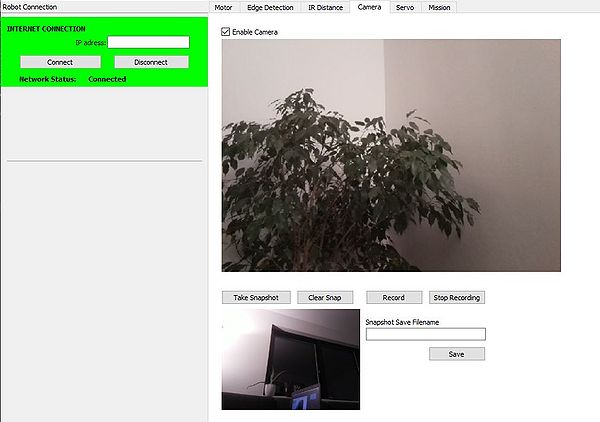
The first thing to do is to design the layout for your mjpeg-streamer. The mjpg-streamer is a command-line application that copies JPEG frames from one or more input plugins to multiple output plugins. The designed Camera window has been designed as in the following picture. The key tip for designing the mjpeg-streamer in Qt-designer, that we are going to use QLabel object for the actual frame where to display the actual live-video footage.
How to set up mjpeg streamer on Raspberry-Pi
Connect to your Raspberry-Pi
$ ssh local@IP(or robot name)
Update the Operating System. *Note that you have to be connected to the network in order to update the software. In some cases, it might be successful, as the robot has not got internet access even though it should have been connected to the internet wirelessly - the best and reliable solution is to use an Ethernet cable and connect to the DTU network using some ports, that can be found around the Campus.
$ sudo apt-get update
Enable the camera and Launch raspi-config:
$ sudo raspi-config
From the menu options:
Select:
6. Enable Camera
Click: Yes
Click: OK
Click: Finish
To download the project you will need a source control system called git. It may not be installed on a fresh image. I know it’s not on the lite image. So you may need to install it.
$ sudo apt-get install git
Now that you have git installed, use it to clone a copy of the mjpg-streamer to your Pi.
$ git clone https://github.com/jacksonliam/mjpg-streamer.git
After the cloned copy of the mjpeg-stream has been coppied to the raspberry-pi, follow these steps.
$ cd mjpg-streamer/
$ cd mjpg-streamer-experimental/
$ sudo apt-get install cmake
$ sudo apt-get install python-imaging
$ sudo apt-get install libjpeg-dev
$ make CMAKE_BUILD_TYPE=Debug
$ sudo make install
When all the necessary libraries have been installed, it is necessary to run the following script to make this setting permanent.
$ export LD_LIBRARY_PATH=.
Now everything is set to runt the streamer:
*If you are running from the root folder, remember to go to the folder ->
$ cd mjpg-streamer/
$ cd mjpg-streamer-experimental/
$ ./mjpg_streamer -o "output_http.so -w ./www" -i "input_raspicam.so"
If the picture is reversed, use this function to display to run the stream:
$ ./mjpg_streamer -o "output_http.so -w ./www" -i "input_raspicam.so -hf"
It is possible to also see the stream using the Web-browser using the host address. This is convinient way how to test if the streamer works correctly.
http://'robotname'.local:8080/?action=stream
To get a snapshot of the current stream use this:
http://'robotname'.local:8080/?action=snapshot
To implement the mjpeg-streamer also requires open cv library installed on your machine. This way the image can be displayed using the open-cv framework.
$ pip install opencv-python
import cv2
As the Video stream will need to happen simultaneously to other robot actions, we pass the Qthread as an argument for this class, which will treat this function as a parallel thread to the main function. Using the open-cv library we are able to capture a video stream and converting it to the Qt format in which we will be able to display the actual image to the Qlabel object.
class VideoThread(QThread):
   change_pixmap_signal = pyqtSignal(np.ndarray)
   def __init__(self):
       super().__init__()
       self._run_flag = True
   def run(self):
       cap = cv2.VideoCapture('http://cleo.local:8080/?action=stream') #
       while self._run_flag:
           ret, cv_img = cap.read()
           if ret:
               self.change_pixmap_signal.emit(cv_img) #cv_img
       cap.release()
   def stop(self):
       self._run_flag = False
       self.wait()
The following functions are crucial to actually display the image onto the label of the Qlabel object. The covert_cv_qt(cv_img) takes the output image of the mjpeg streamer and converts it to the qt format so it can be displayed in our Qt Gui application.
   def convert_cv_qt(self, cv_img):
       rgb_image = cv2.cvtColor(cv_img, cv2.COLOR_BGR2RGB)
       h, w, ch = rgb_image.shape
       bytes_per_line = ch * w
       convert_to_Qt_format = QtGui.QImage(rgb_image.data, w, h, bytes_per_line, QtGui.QImage.Format_RGB888)
       p = convert_to_Qt_format.scaled(500, 500, Qt.KeepAspectRatio)
       return QPixmap.fromImage(p)
The update_image() actually updates the image and displays it to the Qlabel. As you can notice, this function uses the convert_cv_qt function to transform the received image in order to display it properly.
   def update_image(self, cv_img):
       if not self.camera_enabled:
           cv_img = cv2.imread('nosignal.png')
       qt_img = self.convert_cv_qt(cv_img)
       self.ui.Stream_Label.setPixmap(qt_img) # Putting image stream on the label
       if self.camera_enabled and self.take_snapshot:
           qt_img = self.convert_cv_qt(cv_img)
           self.snapshot_image = cv_img
           self.ui.Snapshot_Label.setPixmap(qt_img) # Putting snapped image on the frame
           self.take_snapshot = False
Current setup for the Camera includes also the functionality to take a picture and record a video with the camera. It is a little more simple with taking a picture from the stream because we are just taking last snapped image from the update_image() function and save the image under the entered filename using snapshot_save() function. As it can be seen below, the picture by default saves the ".jpg" file with the current date and time. Otherwise, an user can enter the filename that he would like to use and save it under that. And using the opencv function cv2.imwrite() we save the picture.
def snapshot_save(self):
       t = time.gmtime()
       if self.ui.Camera_SnapFilename.text() == "":
           filename = 'snapshot_' + str(t.tm_year) + str(t.tm_mon) + str(t.tm_mday) + "_" + str(t.tm_hour) + str(t.tm_min) + str(t.tm_sec) +'.jpg'
       else:
           filename = str(self.ui.Camera_SnapFilename.text() + '.jpg')
       cv2.imwrite(filename, self.snapshot_image) # Saving the image under the filename
To record the video from the video stream, the other class was implemented which took care of the video recording functionality.
The key two functions to ensure the video starting/stopping and saving the video are the following. video_StartRecording() functions connects the update_image() function with the video recording thread and starts it. The video_recording flag is True.
   def video_StartRecording(self):
       self.video_recording = True
       if self.video_recording and self.wifiConnected:
           self.VideoRecordingThread = VideoRecordingThread()
           self.VideoRecordingThread.change_pixmap_signal.connect(self.update_image)
           self.VideoRecordingThread.start()
           self.ConsoleMessage += "*Recording...\n"
           self.ConsoleMessagePush = True
Meanwhile, the recording is happening, the toogleRecLabel(), makes the recording status label visible, which indicates that the recording is happening. And the
   def toogleRecLabel(self):
       self.toogleSignalON = not self.toogleSignalON
       if self.toogleSignalON:
           self.ui.VideoRecording_Label.setHidden(True)
       else:
           self.ui.VideoRecording_Label.setHidden(False)
Similarly, the video_StopRecording() function stops the video recording by stopping the video thread and setting the video_recording flag to False.
   def video_StopRecording(self):
       if self.video_recording and self.wifiConnected:
           self.VideoRecordingThread.stop()
           self.ConsoleMessage += "*Recording Stopping...\n"
           self.ConsoleMessagePush = True
       self.ui.VideoRecording_Label.setHidden(True)
       self.video_recording = False
The actual Video recording class that controls the video recording can be seen below. The function out = cv2.VideoWriter('PiVideo_1.avi',cv2.VideoWriter_fourcc('M','J','P','G'), 10, (frame_width,frame_height)) defines the output object and the cv_img = cap.read() and out.write(cv_img) gets the actual image from the cv2.VideoCapture() and then writes the image to the actual output video file.
class VideoRecordingThread(QThread):
   change_pixmap_signal = pyqtSignal(np.ndarray)
   def __init__(self):
       super().__init__()
       self._run_flag = True
   def run(self):
       cap = cv2.VideoCapture('http://cleo.local:8080/?action=stream')
       frame_width = int(cap.get(3))
       frame_height = int(cap.get(4))
       out = cv2.VideoWriter('PiVideo_1.avi',cv2.VideoWriter_fourcc('M','J','P','G'), 10, (frame_width,frame_height))
       while self._run_flag:
           ret, cv_img = cap.read()
           if ret:
               out.write(cv_img)
       cap.release()
       out.release()
   def stop(self):
       self._run_flag = False
       self.wait()
Source Code
The Full Source code can be seen in the following link ->
