Robobot circuits
Back to Robobot_B
Contents |
Digital IO
Circuit diagram
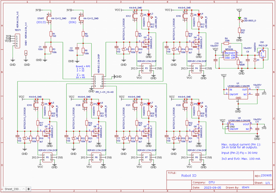
Figure 1. The circuit diagram should ensure that each IO pin can function as both input and output. If input, then the pin has active pull down, i.e. for input to change, it must be pulled high, to at least 3.3V, but 5 or 12V will work too. If output, then a transistor is active when output is high, and can draw at least 1A from the 12V supply. The 5V and 3.3V can supply no more than 100mA.
PCB
Figure 2. The PCB layout for the digital IO circuit.
Regbot
Circuit diagram
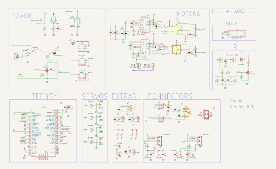
Figure 3. The Regbot circuit.
PCB - 3D view
PCB
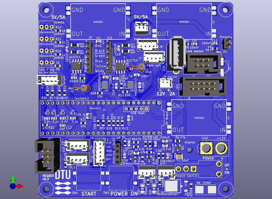
Figure 4. Ecpected view of PCB.
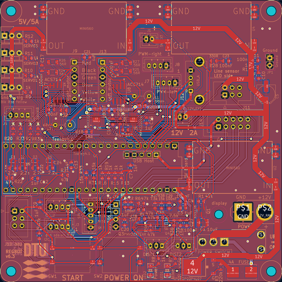
Figure 5. PCB with more trace details.
Line sensor
Circuit
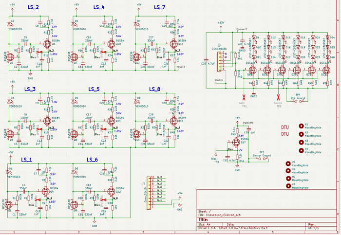
Figure 6. Circuit diagram for the line sensor. 8 sensors with a change amplifier and analog output. The 18 LEDs provides the blinking light (1kHz).
PCB
Figure 7. The PCB in 3D view. The distance from the first to the last sensor is 12cm.
Figure 8. PCB layout.
Raspberry PI
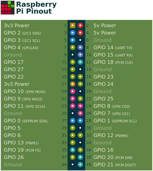
Figure 9. GPIO pin numbers.
