PCB
From Rsewiki
(Difference between revisions)
| Line 11: | Line 11: | ||
* IMU3, SCL2, pin 3_4, AD0 = HIGH, Foot. | * IMU3, SCL2, pin 3_4, AD0 = HIGH, Foot. | ||
* IMU4, SCL2, pin 3_4, AD0 = NC, Hip. | * IMU4, SCL2, pin 3_4, AD0 = NC, Hip. | ||
| + | |||
| + | ==Cables in leg== | ||
[[File:cables-in-leg.png |700px]] | [[File:cables-in-leg.png |700px]] | ||
| Line 16: | Line 18: | ||
Figure 2. Overview of cables in one leg with some wire details. The connection to robot base platform is 24V (10A) and USB only. | Figure 2. Overview of cables in one leg with some wire details. The connection to robot base platform is 24V (10A) and USB only. | ||
Steering servo should be in RC servo interface mode | Steering servo should be in RC servo interface mode | ||
| + | |||
| + | ==Controller block diagram== | ||
| + | |||
[[File:leg_teensy-block-function.png | 700px]] | [[File:leg_teensy-block-function.png | 700px]] | ||
Figure 3. Functional blockdiagram og Teensy controller board. Not all blocks and MAV messages are implemented yet. | Figure 3. Functional blockdiagram og Teensy controller board. Not all blocks and MAV messages are implemented yet. | ||
| + | |||
| + | ==Teensy board and schematic== | ||
[[File:leg_teensy_board.png | 600px]] | [[File:leg_teensy_board.png | 600px]] | ||
Figure 4. Layout of PCB (designed in Eagle). | Figure 4. Layout of PCB (designed in Eagle). | ||
| + | |||
| + | |||
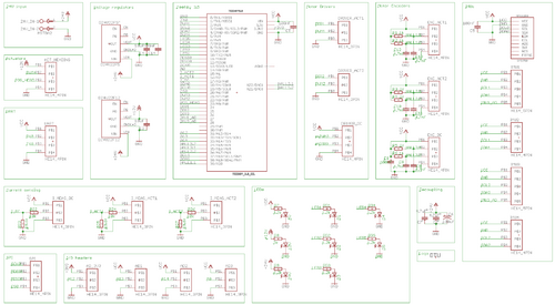
[[File:leg_teensy_schematic.png | 500px]] | [[File:leg_teensy_schematic.png | 500px]] | ||
Figure 5. PCB schematic - click on image to get better view. | Figure 5. PCB schematic - click on image to get better view. | ||
Revision as of 14:30, 8 May 2018
Flexbot PCBs
Contents |
Teensy board
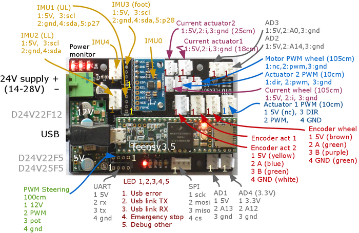
Figure 1. Plug names and pin allocation for Teensy board.
- IMU0, on-board, SCL0, pin 18-19, AD0=NC, Knee.
- IMU1, SCL1, pin 37_38-19, AD0=HIGH, Thigh (upper leg).
- IMU2, SCL1, pin 37_38-19, AD0=NC, Shin (lower leg).
- IMU3, SCL2, pin 3_4, AD0 = HIGH, Foot.
- IMU4, SCL2, pin 3_4, AD0 = NC, Hip.
Cables in leg
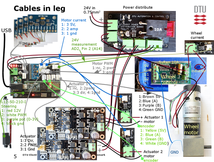
Figure 2. Overview of cables in one leg with some wire details. The connection to robot base platform is 24V (10A) and USB only. Steering servo should be in RC servo interface mode
Controller block diagram
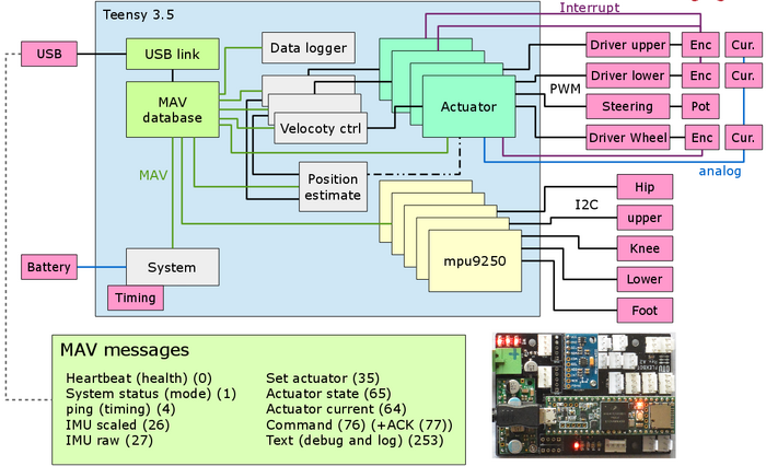
Figure 3. Functional blockdiagram og Teensy controller board. Not all blocks and MAV messages are implemented yet.
Teensy board and schematic
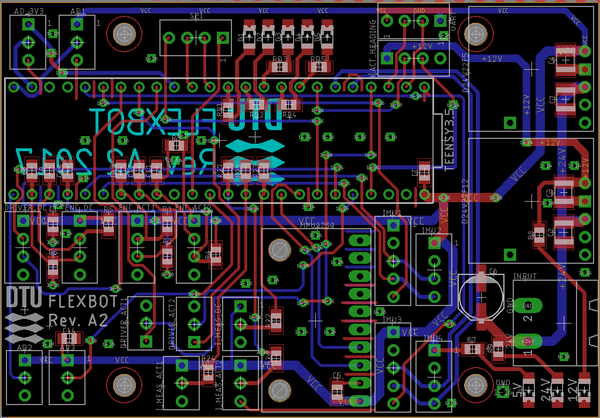
Figure 4. Layout of PCB (designed in Eagle).
Figure 5. PCB schematic - click on image to get better view.
