Control
(→Controller configuration) |
(→Balance point) |
||
| Line 83: | Line 83: | ||
<!-- [[File:Gui_robot.png | 800px]] --> | <!-- [[File:Gui_robot.png | 800px]] --> | ||
| − | [[File:imu_board_orientation.png | | + | [[File:imu_board_orientation.png | 700px]] |
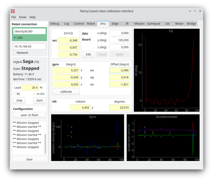
Figure 6. The IMU detects tilt, which should be zero at the balance point. Adjust the IMU board rotation around the y-axis so that the tilt angle is close to zero when the robot is held at the balance point. The board is mounted upside down, and as the centre of gravity is not at the symmetry point, an angle typically around 170 degrees should be found. | Figure 6. The IMU detects tilt, which should be zero at the balance point. Adjust the IMU board rotation around the y-axis so that the tilt angle is close to zero when the robot is held at the balance point. The board is mounted upside down, and as the centre of gravity is not at the symmetry point, an angle typically around 170 degrees should be found. | ||
Revision as of 14:14, 8 January 2023
Back to Regot main page.
The main purpose of the robot is to train control theory.
Contents |
Robot overview
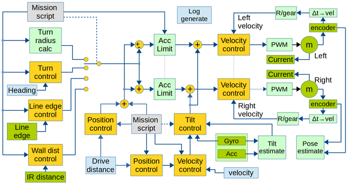
The figure gives the robot functionality with focus on control.
Figure 1. Overview of software data flow. Yellow are the control blocks. Green is hardware (motor and sensors), and light-green is calculations. Light blue is obtained values. Gray is input values.
The sample time for all controllers and data values is 1ms. All software is written in c++, based on Arduino libraries.
Most controllers can be switched off (not enabled). When switched off, there is no connection from reference input to output. If a direct open loop is desired, enable the controller with a Kp = 0 and a feed-forward Kff = 1 (or any other relevant value). This can be valid for measuring the open-loop system in some cases.
Note: The turn-radius controller (top-left) is not a controller but feed-forward only. The nominal speed for each wheel for a given turn radius is calculated, but the resulting turn rate is not measured. The end angle of the turn (part of the tr command line) is measured, but the turn is stopped a bit before the end angle is reached. Subsequently, the specified angle is reached (and controlled by "Turn control") on the following straight path.
Control loop configuration
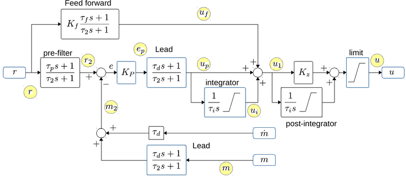
All control blocks (yellow boxes in the figure 1 above) can be configured as P, PI, P-Lead and PI-Lead controllers, with the possibility for a (1st order) prefilter, a (1st order) feed forward and a post integrator. The Lead can be implemented in the forward and return branch, and can also be used more flexible with any pole and zero combination, but all with a steady state gain of 1.
Figure 2. The general PID controller design with additional optional controller parts. "r" is reference input. And after the optional "pre-filter" the reference is compared with the measured value "m", optionally through a Lead filter. The "m-dot" is an optionally derivative of the measurement, that can be used for a less noisy Lead (with tau_d as normal, but no pole). The error signal "e" is fed through a gain "Kp", an optional Lead and an optional integrator. After this the output "u1" is summed from "up" (proportional/Lead), "ui" integrator term and "uf" from an optional feed forward branch. The output "u1" can further optionally be integrated (if Kz=0, if Kz=1 then the post-integrator has a zero). The output is finally limited to signal "u". There is more than one t2 (called tau_pole in the interface) and ti values in the diagram, but they are all individually setable.
All integrators can be limited. The integrators are further disabled if the output limiter limits the output. Some of the control interfaces (all but the balance controllers) further disables integrators when there is defined an acceleration limit in the mission, and these actually are limiting the acceleration.
The "post-integrator" is (mostly) usable in the balance controller.
The "feed forward" is (mostly) usable for the velocity control.
The balance controller replaces the "Lead" after "m" with a "1", and uses tau_d after "m-dot", and "m-dot" is connected to tilt velocity from the gyro (see also figure 1).
The yellow circles show points in the controller that can be logged (with the indicated names), see also User_interface#Data_logger.
Controller configuration
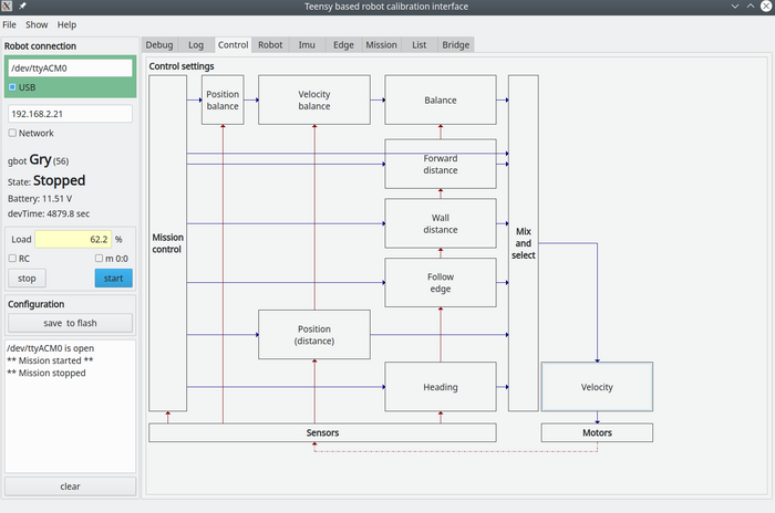
All controllers can be configured from the "control" page of the GUI.
Figure 3. All control values are set from this page, click on the relevant controller and enter the relevant values in the dialogue window shown below.
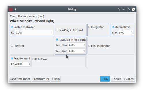
Figure 4. This dialogue configures the wheel velocity controller - shown as a PI-Lead-controller with output limit at (+/-) 9V and a lead term in the feedback branch. A feed-forward is active with a constant gain. All other options are disabled. The blue framed boxes indicate a traditional PID controller with lead in forward (and)/or in the feedback branch.
In figure 4 the control is set to feed-forward only (Kp=0 and a Kf=4), there is further a transfer function in the feedback path with a pole with tau_pole=0.005, a low pass filter with a time constant of 5ms, which for this robot is a good idea the reduce the noise in the velocity measurements.
The output is here limited to +/-9V.
The integrator with an integration limit can be set.
Feedforward is in figure 4 set with a constant gain of 4, but a pole-zero pair could be added too.
NB! As velocity measurements are rather noisy, the filter in the feedback path (Lead/Lag in feed back) could be implemented as a low-pass filter with tau_zero = 0 and tau_pole = 0.005 (recommended).
Calibration
For especially the balance control the gyro offset and the balance point need to be calibrated using the REGBOT GUI application.
IMU
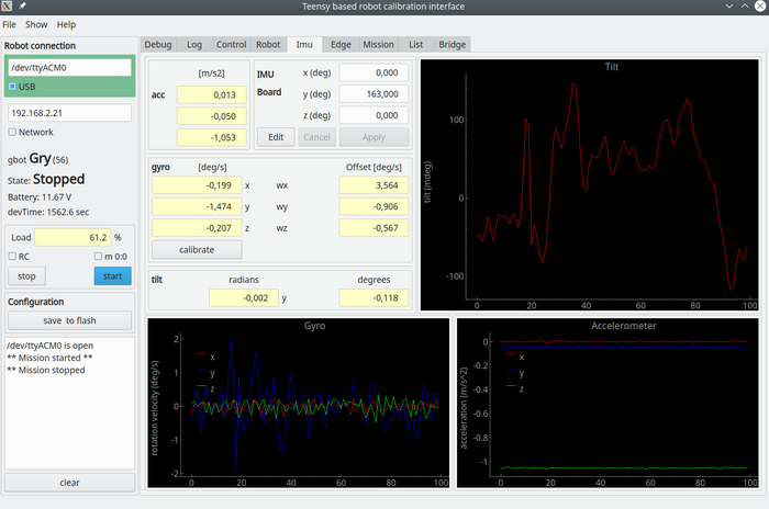
The IMU page shows data from the IMU, and is used for tilt measurement for the balance controller only.
If the "IMU" tab is not visible, then enable it in the "Show" menu line.
Figure 5. IMU data. The graph shows calibrated values, and the gyro is calibrated by keeping the robot stable and press the "calibrate" button. (remember to save the result in robot flash). The servos drift slightly (with e.g. temperature), so repeat if needed.
Balance point
The balance point is set from the "Robot" tab, as shown in figure 6.
Figure 6. The IMU detects tilt, which should be zero at the balance point. Adjust the IMU board rotation around the y-axis so that the tilt angle is close to zero when the robot is held at the balance point. The board is mounted upside down, and as the centre of gravity is not at the symmetry point, an angle typically around 170 degrees should be found.
The balance point can also be set in the field "COG tilt offset" in the Robot tab. This is the angle offset (in radians) so that the zero angle is in the balance point (Center Of Gravity (COG) is just above the wheel support point).
To use, keep the robot at the balance point by hand, read the measured angle in the "tilt [rad]", and if this is not zero (on the first two decimals), then add this tilt value (including sign) to the "COG tilt offset".
To edit the "COG tilt offset" first press "edit", then change the value, press "save" and after that, then also press "Save to robot flash". This should be done if the hardware configuration is changed, e.g. battery change.
