Regbot calibration
(→Edge) |
(→Gyro) |
||
| (22 intermediate revisions by one user not shown) | |||
| Line 1: | Line 1: | ||
| + | Back to [[Regbot]]. | ||
| + | Back to [[Robobot]]. | ||
| + | |||
| + | == Version 2023 == | ||
| + | |||
| + | A number of adjustments have been implemented, but the calibration is the same and should be recognizable. | ||
| + | |||
== Calibration == | == Calibration == | ||
| Line 7: | Line 14: | ||
Figure 1. Basic robot settings. | Figure 1. Basic robot settings. | ||
| − | * "Base WB [m]" is the distance between driving wheels. This is important for heading calculation and turning. | + | * "Base WB [m]"; is the distance between driving wheels. This is important for heading calculation and turning. |
| − | * "gear N" is gear reduction - normally 9.68 | + | * "gear N"; is gear reduction - normally 9.68 on Regbot and 10 or 30 on Robobot |
| − | * "pulses per rev" is encoder configuration - number of pulses for one motor revolution - | + | * "pulses per rev"; is encoder configuration - number of pulses for one motor revolution - is 48 on Regbot and 64 on Robobot motors. |
| − | * "wheel radius" is important for distance calculation | + | * "wheel radius"; is important for distance calculation; adjust so that a 1m in the distance field is 1m in reality. |
| − | * " | + | * "tilt offset"; Center of Gravity tilt offset is important, Calibration is moved to the IMU tab. |
| − | To change, press "edit", do the change and press "save" - and to be permanent after a reboot press "save to flash" | + | To change, press "edit", do the change, and press "save" - and to be permanent after a reboot press "save to flash" |
| − | == | + | == IMU == |
| − | The | + | The IMU (Inertial Measurement Unit) is primarily used when in balance but could be useful for turning as well. |
| − | The gyro has an offset | + | The gyro has an offset that can be calibrated away. |
[[File:gui-imu.png | 800px]] | [[File:gui-imu.png | 800px]] | ||
| − | Figure 2. Gyro calibration. The lower left graph | + | Figure 2. Gyro calibration. The lower left graph is the gyro values when the calibration values are implemented. The lower right graph is the accelerometer (raw) values - no calibration is offered here. The top right graph is the tilt angle - a combination of gyro and accelerometer values (complementary filter). |
| − | * To calibrate, make sure the robot is steady (no movement, no touch) then click the "calibrate" on the "IMU" pane. This will average the values over 1s and use as an offset. | + | * To calibrate, make sure the robot is steady (no movement, no touch), then click the "calibrate" on the "IMU" pane. This will average the values over 1s and use them as an offset. |
| − | * | + | * After this, the 3 gyro values should have zero mean. |
| + | === Balance point (zero tilt) === | ||
| + | |||
| + | <!-- [[File:Gui_robot.png | 800px]] --> | ||
| + | |||
| + | The IMU detects tilt, which should be zero at the balance point. Adjust the IMU board rotation around the y-axis (see Figure 5) so that the tilt angle is close to zero when the robot is held at the balance point. The board is mounted upside down, and as the center of gravity is not at the symmetry point, an angle typically around 170 degrees (Y axis) should be found. | ||
| + | |||
| + | Manually support the robot in the balance point, and adjust the Y-axis rotation until the tilt is close to zero (within 0.5 degrees). | ||
| + | |||
| + | To change the '''IMU board''' angles; press the 'edit', change, and then 'Apply'. | ||
| + | |||
| + | The measured tilt at the balance point should be less than 0.5 degrees. | ||
| + | |||
| + | The balance point can also be fine-tuned in the field "'''tilt offset'''" in the '''Robot''' tab. | ||
| + | |||
| + | To edit the "'''tilt offset'''" first press "'''edit'''", then change the value, press "'''save'''". | ||
| + | |||
| + | * Remember to press "'''Save to flash'''" to use these values after a reboot. | ||
| + | |||
| + | |||
| + | |||
| + | <!-- | ||
== Encoder == | == Encoder == | ||
| Line 42: | Line 70: | ||
* NB! the calibration will only work as long as all encoder tics are counted, i.e. not after a reboot. | * NB! the calibration will only work as long as all encoder tics are counted, i.e. not after a reboot. | ||
| + | --> | ||
== Edge == | == Edge == | ||
| + | |||
| + | Edge sensor is not implemented on most Regbot robots. | ||
Edge (or line) detector for tape lines. | Edge (or line) detector for tape lines. | ||
| Line 93: | Line 124: | ||
The right edge should show about 0, i.e. the robot center line is just above the right edge. | The right edge should show about 0, i.e. the robot center line is just above the right edge. | ||
| − | The part of the surface that is not the white line should have no more than 80% of the reflection of the white line. | + | The part of the surface that is not the white line should have no more than 80% of the reflection of the white line (at the color of the LED). |
=== Crossing detect === | === Crossing detect === | ||
| − | The crossing detect (Crossing det.) value is a | + | The crossing detect (Crossing det.) value basically based on the measured width of the tape. |
| + | |||
| + | If the robot is centered on the one edge, and the tape is more than 3cm wide, then the measured width is 3cm. If the crossing detect threshold is 3 (cm), then it is likely that it will detect it as a crossing line. If the threshold is 5, then a crossing threshold should not be detected. | ||
| + | |||
| + | There is 2 modifiers to this scheme. | ||
| + | |||
| + | * 1. If the width increases with movement, then the increase over the last 2mm of movement will be added to the sensed width. | ||
| + | This means that when approaching a crossing line at an angle, then the triggering of crossing line will be faster. This feature is especially important as there otherwise would be a tendency for the robot to follow the crossing line, or turn a bit in that direction. | ||
| + | |||
| + | Code is like this, with kd = 10 and edgePos2mm is the edge position 2mm ago: | ||
| + | vl = lsLeftSide + (lsLeftSide - edgePos2mm[0]) * kd; | ||
| + | vr = lsRightSide + (lsRightSide - edgePos2mm[1]) * kd; | ||
| + | |||
| + | * 2. If the robot turns (rotates), then the effect in modifier 1 could easily trigger a crossing. To eliminate that the gyro signal around the vertical axis is used to counteract (z axis on REGBOT and x axis on ROBOBOT (on default mounting)). | ||
| + | |||
| + | Code is like this (findCrossingLineVal is the total width before applying the threshold): | ||
| + | const float kg = 0.0005; | ||
| + | // on ROBOBOT z-axis is gyro x, on REGBOT it is z, so add the two | ||
| + | findCrossingLineVal = vr - vl - fabsf(imuGyro[2] + imuGyro[0]) * kg; | ||
| + | |||
| + | If crossing is detected the crossing count increases up to 20, and decreases down to 0 if not. | ||
| + | |||
| + | On figure 4, the threshold is 6.5, i.e. larger than the sensor width, it will then be triggered on fast approach to a line only. | ||
| + | A crossing value of 4.5 is often a good value. | ||
| + | |||
| + | ==== Crossing effect on line edge following ==== | ||
| + | |||
| + | When the crossing line count is > 0 (i.e. at least one crossing detected), then the line follow control will be disabled (the robot will go straight). | ||
== IR distance == | == IR distance == | ||
| − | The | + | The distance sensors need calibration too, but is not needed for the 'control 1' course. |
[[File:gui-ir-2.png | 600px]] | [[File:gui-ir-2.png | 600px]] | ||
Figure 5. Calibration of the IR sensor. | Figure 5. Calibration of the IR sensor. | ||
Latest revision as of 13:19, 7 December 2023
Back to Regbot. Back to Robobot.
Contents |
[edit] Version 2023
A number of adjustments have been implemented, but the calibration is the same and should be recognizable.
[edit] Calibration
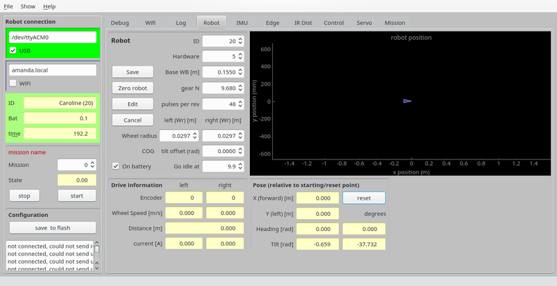
In the REGBOt GUI, the "robot" pane has the basic configuration
Figure 1. Basic robot settings.
- "Base WB [m]"; is the distance between driving wheels. This is important for heading calculation and turning.
- "gear N"; is gear reduction - normally 9.68 on Regbot and 10 or 30 on Robobot
- "pulses per rev"; is encoder configuration - number of pulses for one motor revolution - is 48 on Regbot and 64 on Robobot motors.
- "wheel radius"; is important for distance calculation; adjust so that a 1m in the distance field is 1m in reality.
- "tilt offset"; Center of Gravity tilt offset is important, Calibration is moved to the IMU tab.
To change, press "edit", do the change, and press "save" - and to be permanent after a reboot press "save to flash"
[edit] IMU
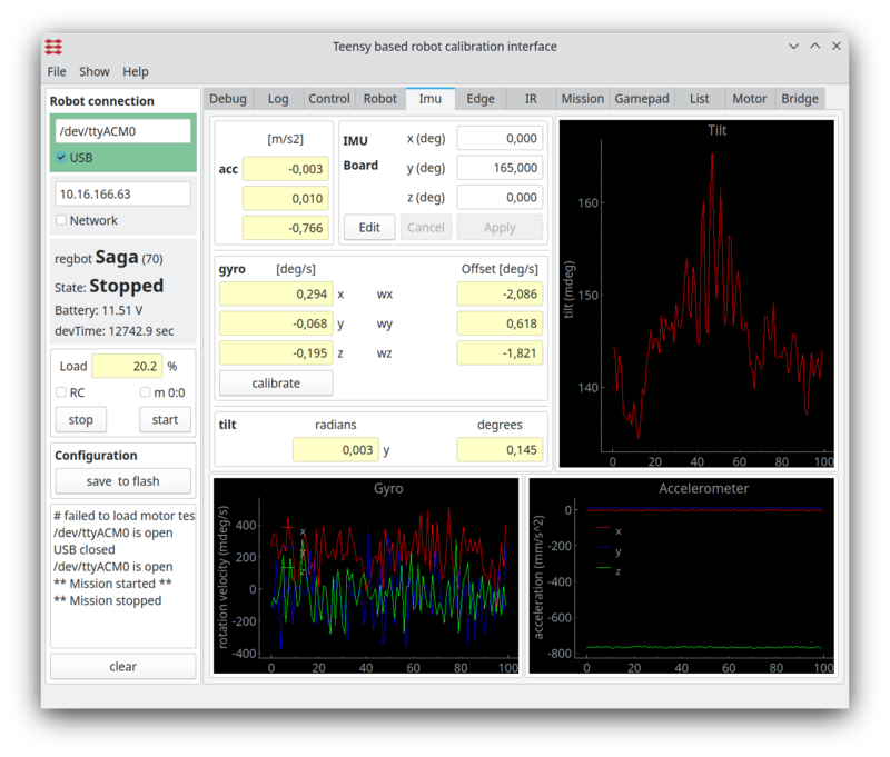
The IMU (Inertial Measurement Unit) is primarily used when in balance but could be useful for turning as well. The gyro has an offset that can be calibrated away.
Figure 2. Gyro calibration. The lower left graph is the gyro values when the calibration values are implemented. The lower right graph is the accelerometer (raw) values - no calibration is offered here. The top right graph is the tilt angle - a combination of gyro and accelerometer values (complementary filter).
- To calibrate, make sure the robot is steady (no movement, no touch), then click the "calibrate" on the "IMU" pane. This will average the values over 1s and use them as an offset.
- After this, the 3 gyro values should have zero mean.
[edit] Balance point (zero tilt)
The IMU detects tilt, which should be zero at the balance point. Adjust the IMU board rotation around the y-axis (see Figure 5) so that the tilt angle is close to zero when the robot is held at the balance point. The board is mounted upside down, and as the center of gravity is not at the symmetry point, an angle typically around 170 degrees (Y axis) should be found.
Manually support the robot in the balance point, and adjust the Y-axis rotation until the tilt is close to zero (within 0.5 degrees).
To change the IMU board angles; press the 'edit', change, and then 'Apply'.
The measured tilt at the balance point should be less than 0.5 degrees.
The balance point can also be fine-tuned in the field "tilt offset" in the Robot tab.
To edit the "tilt offset" first press "edit", then change the value, press "save".
- Remember to press "Save to flash" to use these values after a reboot.
[edit] Edge
Edge sensor is not implemented on most Regbot robots.
Edge (or line) detector for tape lines.
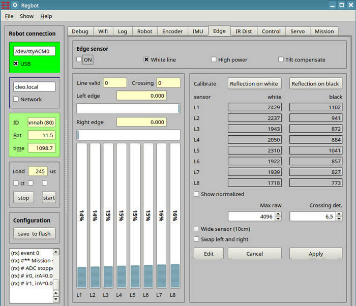
Figure 4. Calibration line sensor.
[edit] Function
The sensor use blinking LEDs - on in 0.5ms and off in 0.5ms - the detected difference is converted to a value between 0 (black) and 4096 (high refection). The censor has automatic offset and is fairly linear within a wide range of ambient illumination.
Direct sunlight will in most cases saturate the sensor.
LED illumination with a blink frequency close to 1 kHz will disturb the sensor.
[edit] Turn on
Turn on line sensor by ticking the "on" field.
Select "White line" - system is never tested on a black line (may/2019).
High power and tilt compensate should only be used when regot is in balance.
To change, pres first the edit button, and when finished press the apply button (followed by the "save to flash" to make sure it stays after a reboot.
[edit] Edge sensor calibration
Place the robot so that the illuminated area is on the white part of the (tape) line, and the robot is in its normal configuration (i.e. all wheels on the ground).
The bars should be more than half filled and not saturated, and flickering slightly. Now, press the "calibrate on white", then the new calibration values will be shown for all 8 sensors.
Lift the robot, so that the sensor sees nothing and press "reflection on black".
Again press "apply" and "save to flash" to save.
[edit] test edge
Place the robot so that the left side of sensor sees the white tape and the right side do not.
The Line valid count should increase fast to 20 (the counter increase or decrease by one dependent on detection or not of a white area (white is about 80% or more of the calibrated white value). So 20 means that a line is detected in (at least) 20 ms.
One missed detection will decrease the count to 19, so a line valid test of maybe 15 should give a reliable measure of a valid line. But a value 15 will means the line has been present for at least 15ms.
White all the way to the left side of sensor yields -3 for the left edge, i.e. the robot (sensor) centerline is -3 cm to the left (3 cm to the right) of the left edge.
The right edge should show about 0, i.e. the robot center line is just above the right edge.
The part of the surface that is not the white line should have no more than 80% of the reflection of the white line (at the color of the LED).
[edit] Crossing detect
The crossing detect (Crossing det.) value basically based on the measured width of the tape.
If the robot is centered on the one edge, and the tape is more than 3cm wide, then the measured width is 3cm. If the crossing detect threshold is 3 (cm), then it is likely that it will detect it as a crossing line. If the threshold is 5, then a crossing threshold should not be detected.
There is 2 modifiers to this scheme.
- 1. If the width increases with movement, then the increase over the last 2mm of movement will be added to the sensed width.
This means that when approaching a crossing line at an angle, then the triggering of crossing line will be faster. This feature is especially important as there otherwise would be a tendency for the robot to follow the crossing line, or turn a bit in that direction.
Code is like this, with kd = 10 and edgePos2mm is the edge position 2mm ago:
vl = lsLeftSide + (lsLeftSide - edgePos2mm[0]) * kd;
vr = lsRightSide + (lsRightSide - edgePos2mm[1]) * kd;
- 2. If the robot turns (rotates), then the effect in modifier 1 could easily trigger a crossing. To eliminate that the gyro signal around the vertical axis is used to counteract (z axis on REGBOT and x axis on ROBOBOT (on default mounting)).
Code is like this (findCrossingLineVal is the total width before applying the threshold):
const float kg = 0.0005;
// on ROBOBOT z-axis is gyro x, on REGBOT it is z, so add the two
findCrossingLineVal = vr - vl - fabsf(imuGyro[2] + imuGyro[0]) * kg;
If crossing is detected the crossing count increases up to 20, and decreases down to 0 if not.
On figure 4, the threshold is 6.5, i.e. larger than the sensor width, it will then be triggered on fast approach to a line only. A crossing value of 4.5 is often a good value.
[edit] Crossing effect on line edge following
When the crossing line count is > 0 (i.e. at least one crossing detected), then the line follow control will be disabled (the robot will go straight).
[edit] IR distance
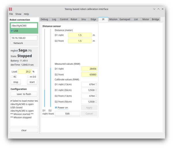
The distance sensors need calibration too, but is not needed for the 'control 1' course.
Figure 5. Calibration of the IR sensor.


