Drone control hardware
(→Flight controller) |
|||
| (26 intermediate revisions by one user not shown) | |||
| Line 1: | Line 1: | ||
back to [[Drone control]] | back to [[Drone control]] | ||
| + | |||
| + | ==Flight controller== | ||
| + | |||
| + | |||
| + | [[File:flight_ctrl_2.png | 500px]] | ||
| + | [[File:flight_ctrl_2_PCB.png | 500px]] | ||
| + | [[File:flight_ctrl_2_PCB_man.png | 600px]] | ||
| + | |||
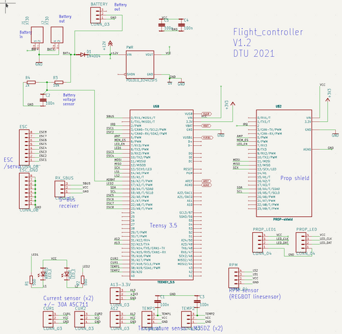
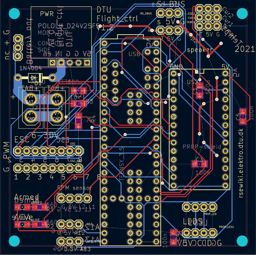
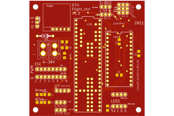
| + | Version 1.2 schematic and PCB-layout. Sonar height is connected to RX4 same pin as A12 (marked as A12 on board) and 5V. Angle IMU for motor angles are GY91 boards connected to I2C-2, using pin 3 (SCL) and 4 (SDA) marked on board as ESC 1 (SCL) and ESC2 (SDA), both on 3.3V from pins marked A13 and 3.3V. | ||
| + | Current measurements are not used (one is shorted). ESC 1 and 2 are moved to ESC 7 and 8. | ||
| + | |||
| + | |||
| + | ===Prop Shield === | ||
| + | |||
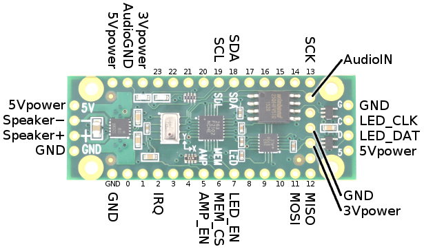
| + | From: https://www.pjrc.com/store/prop_shield.html | ||
| + | |||
| + | [[File:propshield_pinout.png]] | ||
| + | |||
| + | Signal Pin # Used By: Description | ||
| + | SDA 18 sensors I2C Data for motion sensors | ||
| + | SCL 19 sensors I2C Clock for motion sensors | ||
| + | IRQ 2 sensors Interrupt from motion sensors | ||
| + | MOSI 11 memory,led SPI Data | ||
| + | MISO 12 memory SPI Data | ||
| + | SCK 13 memory,led SPI Clock | ||
| + | MEM_CS 6 memory Low to access memory | ||
| + | LED_EN 7 led High to send LED data | ||
| + | LED_DAT - led 5v buffered LED Data output | ||
| + | LED_CLK - led 5v buffered LED Clock output | ||
| + | AMP_EN 5 amp High to enable amplifier | ||
| + | AudioIN DAC amp Audio signal | ||
| + | AudioGND AGND amp Audio ground | ||
| + | Speaker+ - amp Connect a 4Ω or 8Ω speaker | ||
| + | Twisted pair wire is recommended | ||
| + | Speaker - - amp | ||
| + | 5Vpower VIN amp,led | ||
| + | 3Vpower 3.3V sensors,memory | ||
| + | GND GND (all) | ||
| + | |||
| + | ==== Schematic ==== | ||
| + | |||
| + | [[File:propshield_schematic.png]] | ||
| + | |||
| + | Sensor board | ||
| + | |||
| + | ==Servo power board== | ||
| + | |||
| + | [[File:servo_distribute.png | 500px]] | ||
| + | [[File:servo_distribute_PCB.png | 500px]] | ||
| + | [[File:servo_distribute_PCB_man.png | 500px]] | ||
| + | |||
| + | Interface and power board for servos. PWM comes from pins marked PWM from the Teensy, corresponding servo gets power and PWM from pins marked Servo. PWM 1..4 are powered by one 6V buck converter (PWM1 is used for the right servo). The other 6V buck converter is available on the 2x3 pins bottom right on PCM figure marked 5V1 and 5V2 (used for right servo). The patch is needed to supply power to the servo (one for each of the four PWM sets. PWM pin is to the right on the PCB figures. | ||
| + | |||
| + | ==Power distribute== | ||
| + | |||
| + | [[File:power_distribute.png | 400px]] | ||
| + | [[File:power_distribute_PCB.png | 500px]] | ||
| + | [[File:power_distribute_PCB_man.png | 600px]] | ||
| + | |||
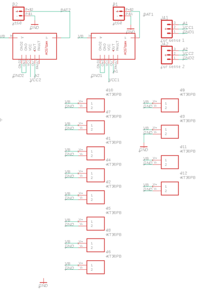
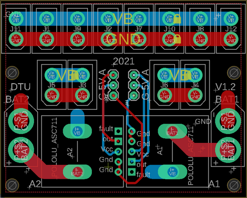
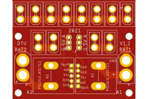
| + | Power distribution from 2 batteries in parallel using XT60, all output sockets are XT30. Both current-sense PCBs are not used, one is broken and is just shorted. | ||
Latest revision as of 12:12, 5 May 2023
back to Drone control
Contents |
[edit] Flight controller
Version 1.2 schematic and PCB-layout. Sonar height is connected to RX4 same pin as A12 (marked as A12 on board) and 5V. Angle IMU for motor angles are GY91 boards connected to I2C-2, using pin 3 (SCL) and 4 (SDA) marked on board as ESC 1 (SCL) and ESC2 (SDA), both on 3.3V from pins marked A13 and 3.3V. Current measurements are not used (one is shorted). ESC 1 and 2 are moved to ESC 7 and 8.
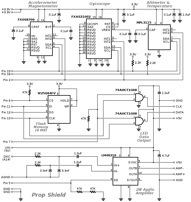
[edit] Prop Shield
From: https://www.pjrc.com/store/prop_shield.html
Signal	  Pin #	Used By:	Description
SDA	  18	sensors	I2C Data for motion sensors
SCL	  19	sensors	I2C Clock for motion sensors
IRQ	  2	sensors	Interrupt from motion sensors
MOSI	  11	memory,led	SPI Data
MISO	  12	memory	SPI Data
SCK	  13	memory,led	SPI Clock
MEM_CS	  6	memory	Low to access memory
LED_EN	  7	led	High to send LED data
LED_DAT  -	led	5v buffered LED Data output
LED_CLK  -	led	5v buffered LED Clock output
AMP_EN	  5	amp	High to enable amplifier
AudioIN  DAC	amp	Audio signal
AudioGND AGND	amp	Audio ground
Speaker+ -	amp	Connect a 4Ω or 8Ω speaker
                       Twisted pair wire is recommended
Speaker  -	-	amp
5Vpower  VIN	amp,led
3Vpower  3.3V	sensors,memory
GND	  GND	(all)
[edit] Schematic
Sensor board
[edit] Servo power board
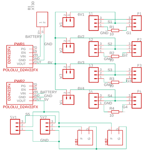
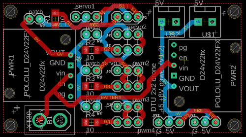
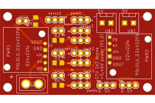
Interface and power board for servos. PWM comes from pins marked PWM from the Teensy, corresponding servo gets power and PWM from pins marked Servo. PWM 1..4 are powered by one 6V buck converter (PWM1 is used for the right servo). The other 6V buck converter is available on the 2x3 pins bottom right on PCM figure marked 5V1 and 5V2 (used for right servo). The patch is needed to supply power to the servo (one for each of the four PWM sets. PWM pin is to the right on the PCB figures.
[edit] Power distribute
Power distribution from 2 batteries in parallel using XT60, all output sockets are XT30. Both current-sense PCBs are not used, one is broken and is just shorted.
