Regbot version 5
From Rsewiki
(Difference between revisions)
(→Schematic) |
(→Error list) |
||
| (5 intermediate revisions by one user not shown) | |||
| Line 11: | Line 11: | ||
== Schematic == | == Schematic == | ||
| − | [[File:Regbot_v5.0_schematic.png | | + | [[File:Regbot_v5.0_schematic.png | 1000px]] |
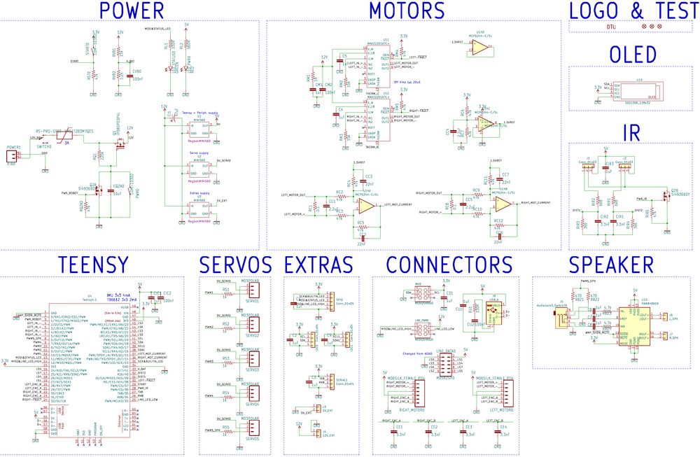
Schematic of version 5.0 (a few mods for version 5.1) | Schematic of version 5.0 (a few mods for version 5.1) | ||
| + | |||
| + | === Error list === | ||
| + | |||
| + | * 5V and 12V PCB sockets, here the silk-screen indicates a wrong orientation. | ||
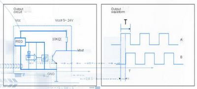
| + | * The motor encoder delivers 5V for the encoder signals, Teensy 4.1 is not 5V tolerant (but the output is open-collector with 10kOhm to 5V, so should be OK). | ||
| + | [[File:encoder_circuit_from_alsongdcmotor.png | 400px]] | ||
Latest revision as of 11:36, 1 November 2022
Back to Regbot
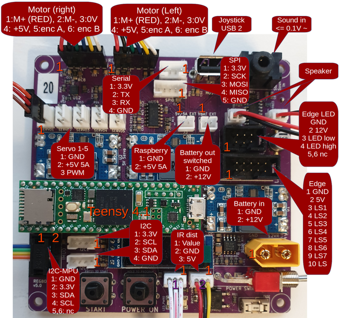
Info about Regbot PCB, diagram and plugs.
[edit] Base board
PCB layout (Version 5.1 has minor changes only)
[edit] Schematic
Schematic of version 5.0 (a few mods for version 5.1)
[edit] Error list
- 5V and 12V PCB sockets, here the silk-screen indicates a wrong orientation.
- The motor encoder delivers 5V for the encoder signals, Teensy 4.1 is not 5V tolerant (but the output is open-collector with 10kOhm to 5V, so should be OK).


