Drone control hardware
From Rsewiki
(Difference between revisions)
(→Schematic) |
(→Schematic) |
||
| Line 7: | Line 7: | ||
[[File:flight_ctrl_2.png | 700px]] | [[File:flight_ctrl_2.png | 700px]] | ||
| − | |||
| − | |||
[[File:flight_ctrl_2_PCB.png | 700px]] | [[File:flight_ctrl_2_PCB.png | 700px]] | ||
| − | + | Version 1.2 schematic and PCB-layout. | |
==PCB== | ==PCB== | ||
Revision as of 10:46, 5 May 2023
back to Drone control
Contents |
Schematic
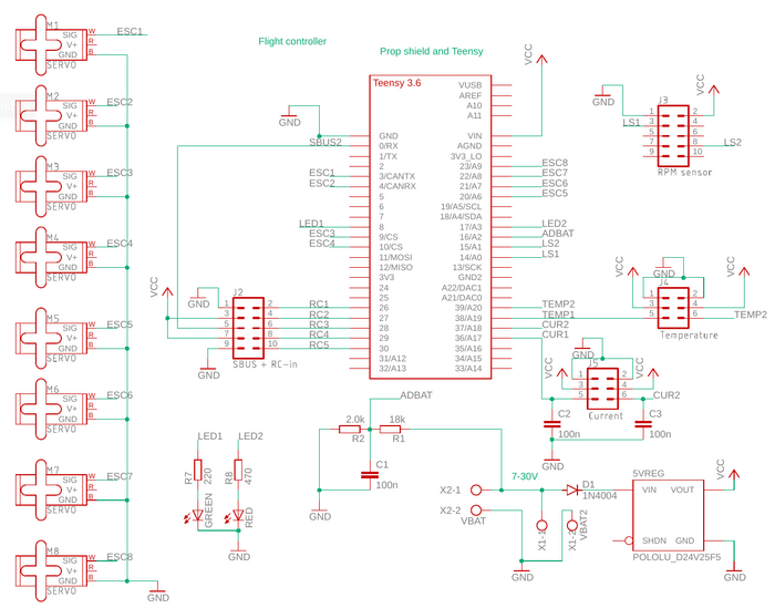 Version 1.0 schematic, sensor board is not shown (mounted on top of Teensy).
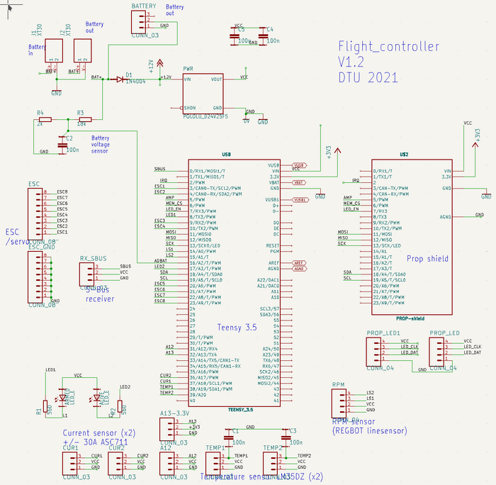
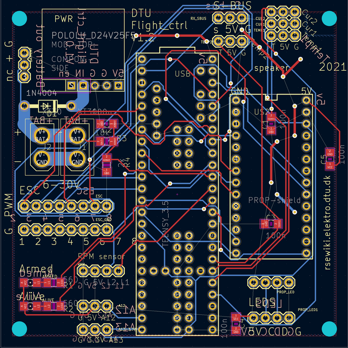 Version 1.2 schematic and PCB-layout.
PCB
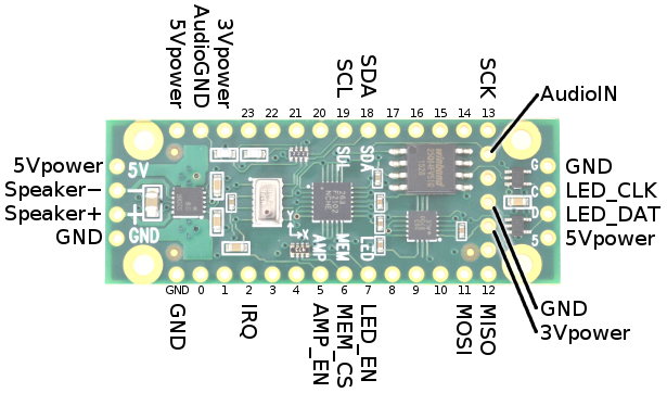
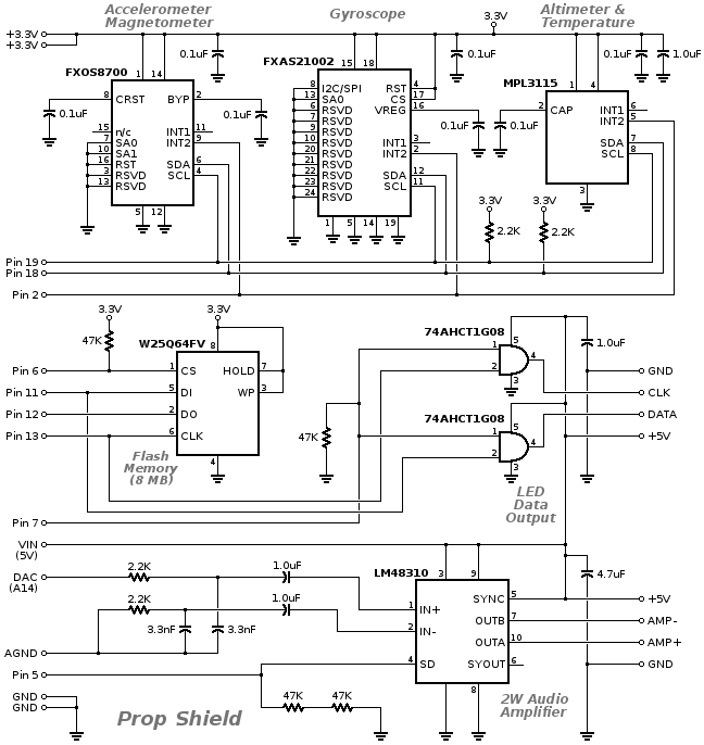
Prop Shield
From: https://www.pjrc.com/store/prop_shield.html
Signal	  Pin #	Used By:	Description
SDA	  18	sensors	I2C Data for motion sensors
SCL	  19	sensors	I2C Clock for motion sensors
IRQ	  2	sensors	Interrupt from motion sensors
MOSI	  11	memory,led	SPI Data
MISO	  12	memory	SPI Data
SCK	  13	memory,led	SPI Clock
MEM_CS	  6	memory	Low to access memory
LED_EN	  7	led	High to send LED data
LED_DAT  -	led	5v buffered LED Data output
LED_CLK  -	led	5v buffered LED Clock output
AMP_EN	  5	amp	High to enable amplifier
AudioIN  DAC	amp	Audio signal
AudioGND AGND	amp	Audio ground
Speaker+ -	amp	Connect a 4Ω or 8Ω speaker
                       Twisted pair wire is recommended
Speaker  -	-	amp
5Vpower  VIN	amp,led
3Vpower  3.3V	sensors,memory
GND	  GND	(all)
