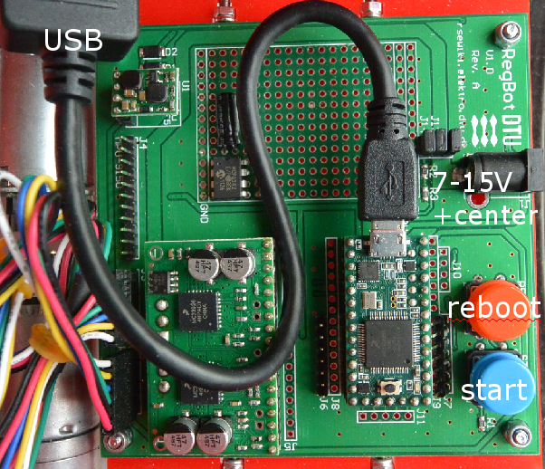
Regbot
Small robot intended for control-1 exercises.
Contents |
Hardware status
REGBOT comes in 2 versions:
- version 1A - with robot number 1..15
- version 2B - with robot number 16..36
Software download
- Robot software (regbot.hex): 2.241
- Client software for windows (regbot.exe): 2.247
(as of 1 January 2016)
repository for software - client and robot
On a Linux computer do something like this:
svn co svn://repos.gbar.dtu.dk/jcan/regbot/regbot .
svn co svn://repos.gbar.dtu.dk/jcan/regbot/qtgui .
Install software
Get the regbot.exe from the course homepage, place it in a directory, this directory will be default for configuration file and result files from the robot.
A driver must be installed to get in contact with the robot - see installation in windows
The driver will create a com-port when connected - most likely com3 or any higher number. When the robot is disconnected by unplugging the cable, then the client needs to be restarted if it was connected when the cable was unplugged (no connection detect in windows).
- Software installation and tool-chain - Linux
- installation in windows some of the tool-chain
- Schematic
User interface
The user interface can configure and run the robot, as well as inspecting almost all values on the robot. Written in python using Qt GUI library.
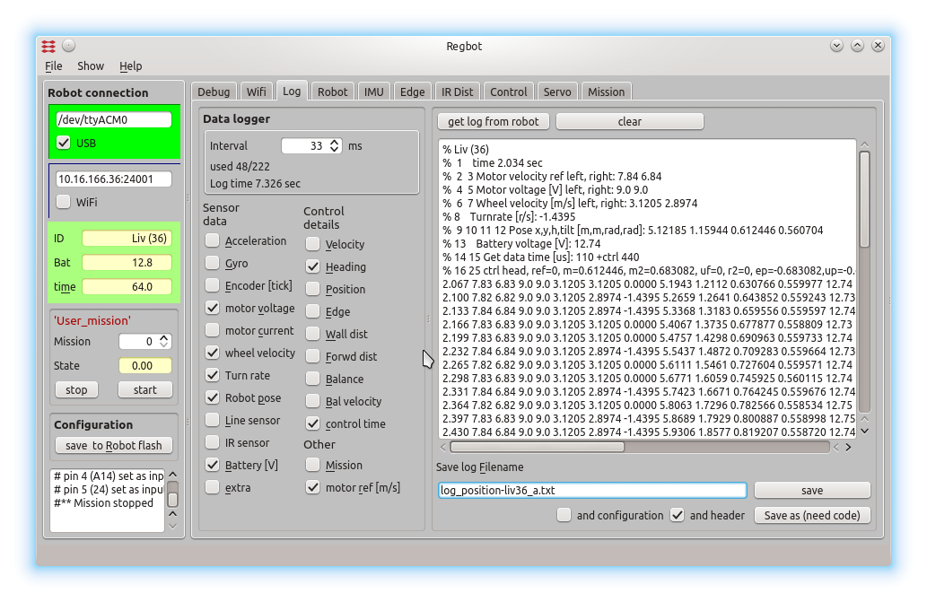
The GUI allows to make step responses for velocity and turn. The step response is recorded in a buffer on the robot and is fetched in a MATLAB style file (as shown). Interface points that are recorded can be switched on and off to better utilize the limited buffer size on the robot (35kBytes).
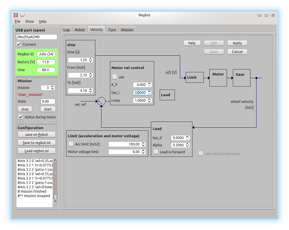
This is a page to make a step response and insert controller values for velocity control. The same controller is used for both wheels.
Design overview hardware
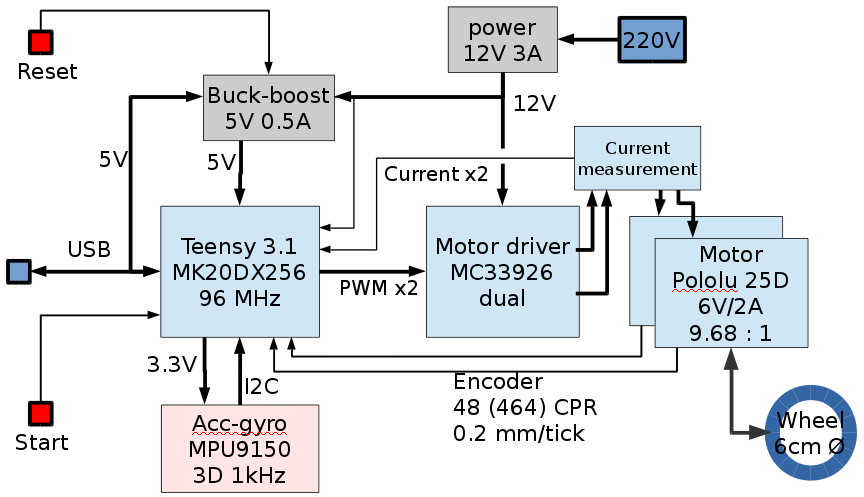
Hardware blockdiagram. Most blocks are off-the-shelf hardware modules from PJRC (Teensy), Pololu (motor, driver and buck-boost converter) and Sparkfun (IMU).
A line sensor is planned, but not implemented yet.
Design overview software
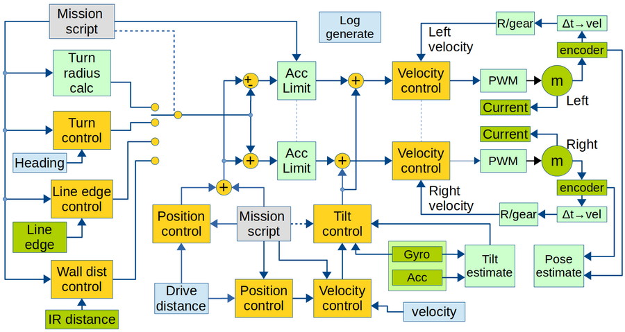
Overview of software data flow. Yellow is control blocks. Green is hardware (motor and sensors), Light green is calculations. Light blue is obtained values. Gray is input values.
Sample time for all controllers and data values are 1ms. All software is written in c++, based on Arduino libraries.
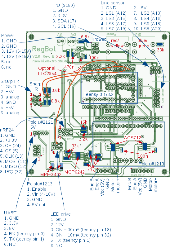
PCB connections revision 2B
Component placement and values (in red) are shown here. Plug connections are shown in blue.
The Sharp IR sensor output is not connected to an AD converter input.
The IR sensor voltage divider output should be between 0 and 1.2V, and could be connected to A0 and A1 (used to be feedback from motor-controller). Unfortunately a plug can not be mounted (space conflict with USB plug).
The orange wires are patches (line sensor low power at pin 32 and from IR sensor to A0 and A1).
Install hardware - version 1A
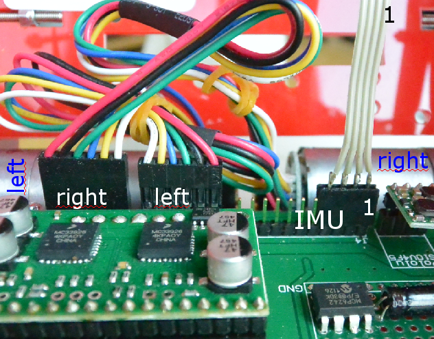
The motor and IMU wires are mounted as shown here. The IMU uses 4 wires only, so only the rightmost pins (1..4) on the main board are used.
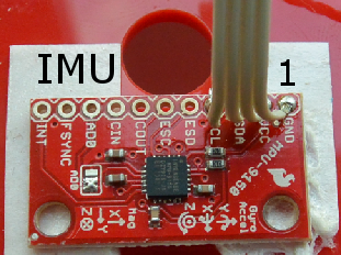
Pin 1 on the IMU is as shown here
The teensy processor and power is connected as shown
