Robobot mission
Back to robobot
Contents |
Robobot mission software
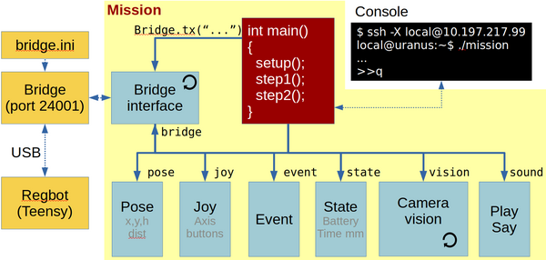
This figure shows the mission functional blocks. The main connection is to the robobot_bridge, through which the robot is controlled. The red mission block is the main block, where the behaviour is controlled. To help decide and control the behaviour, there is a number of data elements available in the bottom row of boxes, available through the bridge. A camera block is available, where image processing is assumed to happen. From the camera block, there is support for ArUco marker detection.
The blocks marked with a circle arrow is running their own thread. The yellow boxes are features available outside the mission application.
The mission application executable is in /home/local/mission/build:
local@solvej:~ $ cd mission/build
local@solvej:~/mission/build $ ./mission
image size 960x1280
Connecting to camera
Connected to pi-camera ='00000000a0604732
# Welcome to REGBOT bridge - send 'help' for more info
# press green to start.
Press h for help (q for quit)
>>
When the application is starting it opens the camera and displays the used image size (960x1280) and the camera serial number 00000000a0604732. Then it connects to the bridge, that reply "# Welcome to REGBOT bridge". The connection to the bridge is strictly needed, otherwise the mission app terminates.
The "# press green to start." is information from the actual mission plan.
There is a prompt at the end ">>" indication that the keyboard is active.
Main
When the mission app is started a number of functions are available from the keyboard.
Press h (and enter) to get a list of features:
>> h
# got 'h' n=1
# mission command options
#    a    Do an ArUco analysis of a frame (no debug - faster)
#    b    Bridge restart
#    c    Capture an image and save to disk (image*.png)
#    d 1/0 Set/clear flag to save ArUco debug images, is=0
#    h    This help
#    lo xxx  Open log for xxx (pose 0, hbt 0, bridge 0, imu 0
#               ir 0, motor 0, joy 0, event 0, cam 0, aruco 0, mission 0)
#    lc xxx  Close log for xxx
#    o    Loop-test for steady ArUco marker (makes logfile)
#    p 99 Camera pan (Yaw) degrees (positive CCV) is 0.0 deg
#    q    Quit now
#    r 99 Camera roll degrees (positive left), is 0.0 deg
#    s    Status (all)
#    t 99 Camera tilt degrees (positive down), is 10.0 deg
#    2 x y h d    To face destination (x,y,h) at dist d
#    3 x y h      Camera position on robot (is 0.030, 0.030, 0.270) [m]
#
# NB!  Robot may continue to move if this app is stopped with ctrl-C.
>>
Log-files can be opened, this is a nice feature for debugging and analyzing sensor behaviour. e.g. the command
>> lo pose hbt imu ir motor joy event cam aruco mission
will open logfiles for most of the available data - except the bridge, that logs all communication.
The camera pose should be set in "ucamera.h", but can temporarily be changed here with the 'p', 'r', 't' and '3' commands.
The status list 's' gives an actual status for rather many data points, including 'data age', the time since the last update.
In the line starting with '3' is shown current camera position on the robot, relative to the centre between the driving wheels at floor level 3cm more forward, 3cm to the left and 27cm above the ground.
Logfiles
The data blocks have a data logger feature that can be enabled and disabled. The interface logfile will be in a text format for MATLAB import. The name of the log-file will include date and time, and will therefore not overwrite the previous logfile.
The IR logfile could be named 'log_irdist_20200105_133333.297.txt' look like this:
% robobot mission IR distance log
% 1 Timestamp in seconds
% 2 IR 1 distance [meter]
% 3 IR 2 distance [meter]
% 4 IR 1 raw [AD value]
% 5 IR 2 raw [AD value]
1578227613.337 0.250 0.730 33549 5864
1578227613.372 0.249 0.740 33649 5687
1578227613.419 0.250 0.759 33476 5330
1578227613.455 0.250 0.716 33468 6147
1578227613.494 0.250 0.727 33470 5936
And can be displayed in MATLAB using a script like this
ir = load('log_irdist_20200105_133333.297.txt'); %
h = figure(300)
hold off
plot(ir(:,1) - ir(1,1), ir(:,2));
hold on
plot(ir(:,1) - ir(1,1), ir(:,3));
grid on
grid MINOR
axis([5,12,0,1])
legend('IR 1 distance', 'IR 2 distance','location','southwest')
xlabel('sec')
ylabel('distance [m]')
saveas(h, 'ir1-ir2.png')
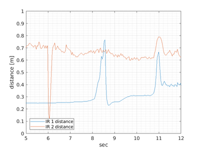
And in this case, the plot shows:
The plot shows that longer distances (IR2) have more noise than shorter distances (IR1). In this case the drive is started by an IR2 distance less than 0.3m (at 6 seconds), hereafter the robot moves and the IR 1 distance (looking right) sees different obstacles.
Bridge
This part handles the interface with the regbot_bridge application. This two-way communication handles each direction individually.
Sending messages is mostly handled by the mission block, here regular updates of data is requested for the data blocks - e.g. robot pose, joystick buttons, IR-sensor measurements etc.
The receiving part of the bridge is always waiting for messages and distribute them for the relevant data block for decoding.
In a normal setup, about 150 messages will be received each second.
Data elements
This is a list of the features of each of the data elements.
IMU
The IMU is an MPU-9150 chip from InvenSense, that provide accelerometer and gyro signals on all 3 axes.
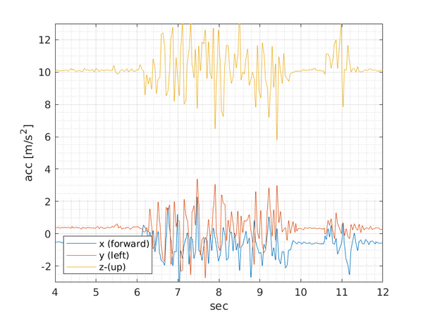
Accelerometer data. The z-axis shows the gravity acceleration, and when the robot starts driving after 6 seconds, there is clearly some bumping, that is seen as noise. The robot holds a pause at about 10 to 10.5 seconds and then turns a bit. The values on the x-axis (forward) ought to show some lateral acceleration, but it is hard to see in the noise.
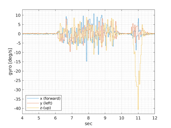
Gyro data. While driving forward (from 6 to 10 seconds) there is a significant amount of noise. The robot holds a pause at about 10 to 10.5 seconds and then turns a bit. The turning (from 10.5 to 11.5 seconds) is clearly visible on the gyro z-axes.
The data is accessible in the mission code as:
bridge->imu->acc[0]   Acceleration in x-axes (forward) [m/s^2]
bridge->imu->acc[1]   y-axis (left)
bridge->imu->acc[2]   z-axes (up)
bridge->imu->gyro[0]  Rotation velocity around x-axes [degree/sec]
bridge->imu->gyro[1]  y-axis
bridge->imu->gyro[2]  z-axes
There is further a turn rate function (vector sum of all three gyro axes):
bridge->imu->turnrate()
There is no calculated nor calibrated scale not offset on the accelerometer reading.
The gyro offset can be calibrated using the REGBOT GUI (IMU tab).
IR-dist
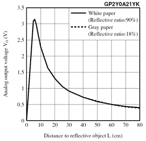
There are two IR sharp sensors type GP2Y0A21, a 10-80cm sensor.
The raw response from the sensor is approximate as shown here
The part from about 8-10cm is converted to a distance in meter using the calibration points in the REGBOT GUI.
A data example is shown above in the logfiles section.
The data is accessible using
bridge->irdist->dist[0]  is distance sensor 1 [m]
bridge->irdist->dist[1]  is distance sensor 2 [m]
Pose
The robot pose includes position, orientation and tilt and is accessed as
bridge->pose->x      distance in x-direction (forward) sinse start of mission.
bridge->pose->y      y-distance
bridge->pose->h      heading in radians, zero is aligned with x-axes, positive is counter clockwise
bridge->pose->tilt   tilt is rotation angle around the y-axis (used for REGBOT balance) (using a complementary filter (acc and gyro).
bridge->pose->dist   distance driven since start of mission [m].
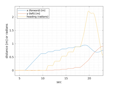
The data from the same mission as above looks like.
The first plot shows that the robot moves 0.6m forward (y=0 and h=0) starting at 6 seconds and stops at 10 seconds - to take an image. After this, it takes a number of turns (about 20 degrees with a turning radius of about 0.2m) with a stop for about a second (looking for an ArUco code in the image).
After 18 seconds and the heading is about 0.9 radians, and an ArUco-code is visible. Thien the robot advances to the position of the code (in a turn-drive-turn manoeuver).
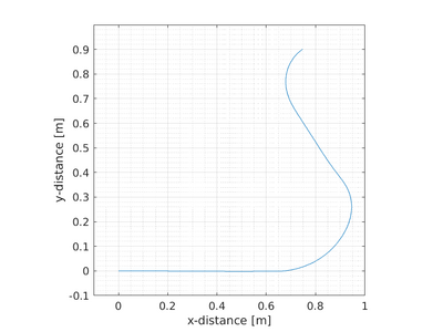
The second plot shows the position of the robot.
Calibration of the odometry is the wheel-base (distance between driving wheels) and the wheel radius. These setting must be inserted in the REGBOT GUI (robot tab).
Joy
The joystick data is available from the bridge.
The following data is available
bridge->joy->axes[0]  (left hand left-right axes)
...
bridge->joy->axis[7]  (digital up-down axes)
For the other axes see Robobot_bridge#Gamepad. The value is a signed 16-bit value (-32767 to 32766) for the axes.
bridge->joy->button[0]    Green button
...
bridge->joy->button[10]   Right knob
For the other buttons see Robobot_bridge#Gamepad. The value is 0 (not pressed) and 1 (pressed).
There is further a flag for manual override by the gamepad
bridge->joy->manual
With true or false value (true means gamepad control)
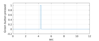
The mission from the other plots gets started with a press on the green button about 4 seconds after the start of the mission application. (the robot then further awaits the distance of IR sensor 2 is below 0.3m before starting to move).
Motor
The motor interface gives the (estimated) velocity of the two driving wheels.
bridge->motor->velocity[0]     Velocity of the left wheel in m/s
bridge->motor->velocity[1]     Velocity of right wheel
There is further access to the motor current.
bridge->motor->current[0]     Current of the left motor in Amps
bridge->motor->current[1]     Current of right motor
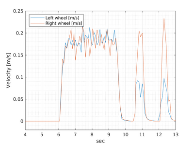
An example from the mission used earlier is shown. The left plot shows the estimated velocity, where the velocity starts after 6 seconds at about 0.2 m/s and going back to zero at about 10 seconds, and after that starts turning at 10.5 and 12 seconds - the right wheel drives faster. It is visible that there is significant noise on the velocity estimate.
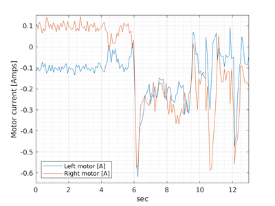
The right current plot shows that the control is active (but not moving) with a current about 100mA. After 6 seconds there is a current peak to about 600mA that starts the motors and then drives with a current of about 250mA. Again after 10.5 and 12 seconds, there is a start-current peak.
Info
The info block holds som static data, but also data from the heartbeat message - the only part that can be logged).
Event
Holds all 32 events. The logfile has a list of when each of then has been set or cleared.
Edge
The edge sensor (also called line sensor).
Camera
The camera interface sets the camera to 1280 x 960 pixels at 30 frames per second.
...
ArUco
This part of the camera system is configured to detect ArUco codes with their position relative to the robot. The position is in (x, y, z), where x is forward, y is left and z is up. The reference position is the center between the driving wheels at ground level.
Mission
The mission block has access to all the other elements and controls the performance of the robot.
The mission code is described in a bit more detail here.
Installation
Get software
Get the ROBOBOT software from the svn repository:
svn checkout svn://repos.gbar.dtu.dk/jcan/regbot/mission mission
or just update if there already
svn up
Compile
To be able to compile the demo software CMAKE needs also to use the user installed library (raspicam installed above), so add the following line to ~/.bashrc:
export CMAKE_PREFIX_PATH=/usr/local/lib
Then build Makefiles and compile:
cd ~/mission
mkdir -p build
cd build
cmake ..
make -j3
Then test-run the application:
./mission
It should print that the camera is open and the bridge is connected to the REGBOT hardware.
Sound
The robot has small speakers
Music
Speak
system("espeak \"bettina reached point 3\" -ven+f4 -a30 -s130");
This line makes the robot say "bettina reached point 3" the parameters "-a30" turns amplitude down to 30%, "-ven+f4" sets language to english with female voice 4 and "-s130" makes the speech a little slower and easier to understand. It requires that espeak is installed (sudo apt install espeak).
To use on Raspberry pi, it is better to use
system("espeak \"Mission paused.\" -ven+f4 -s130 -a60 2>/dev/null &");
The "2>/dev/null" tell that error messages should be dumped, and the final "&" say that it should run in the background (not to pause the mission).
AruCo Marker
The camera class contains some functions to detect Aruco markers. It it described in more details on AruCo Markers.
Software documentation (doxygen)
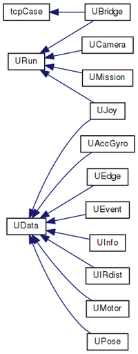
Figure: generated with doxygen http://aut.elektro.dtu.dk/robobot/doc/html/classes.html
The classes that inherit from UData are classes that makes data available for the mission, e.g. joystick buttons (in UJoy) event flags (in UEvent) or IR distance data (in UIRdist).
The classes that inherit from URun has a thread running to receive data from an external source, e.g. UBridge that handles communication with the ROBOBOT_BRIDGE.
The camera class (UCamera) is intended to do the image processing.
HTML documentation - Doxygen
To generate doxygen html files go to mission directory and run doxygen.
cd ~/mission
doxygen Doxyfile
then open the index.html with a browser.
If doxygen is not installed, then install using
sudo apt install doxygen
