Regbot version 4
From Rsewiki
(Difference between revisions)
(→Introduction) |
|||
| (4 intermediate revisions by one user not shown) | |||
| Line 1: | Line 1: | ||
| + | Back to [[Regbot]]. | ||
| + | |||
| + | Back to [[Robobot]]. | ||
| + | |||
== Introduction== | == Introduction== | ||
Version 4 has motor controller on-board and support for servos. | Version 4 has motor controller on-board and support for servos. | ||
This version is powered by a Teensy 3.5 processor (128 kB RAM and 512kB PROM at 120 MHz). | This version is powered by a Teensy 3.5 processor (128 kB RAM and 512kB PROM at 120 MHz). | ||
| + | |||
| + | PCB: savner 12v output til ekstern PSU (raspberry, LED m.v.), udtag efter MOSFET switch. | ||
| + | savner PWM+direction+enable output til extern motor controller. | ||
== Schematic and board == | == Schematic and board == | ||
| Line 17: | Line 24: | ||
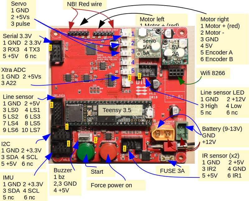
Figure 3. REGBOT main board with annotated connectors. | Figure 3. REGBOT main board with annotated connectors. | ||
| + | |||
| + | [[File:regbot_v4-in-place.jpg]] | ||
| + | |||
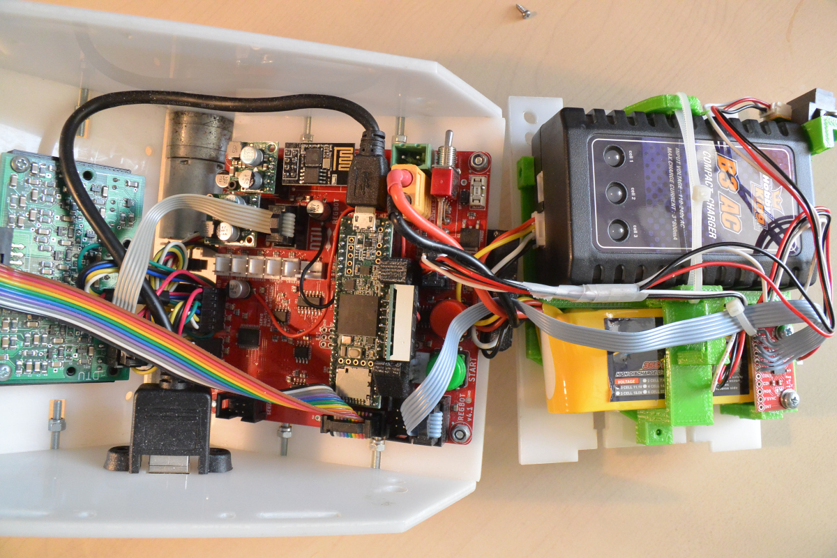
| + | Figure 4. Version 4 board in place. | ||
Latest revision as of 18:00, 14 January 2021
Back to Regbot.
Back to Robobot.
[edit] Introduction
Version 4 has motor controller on-board and support for servos. This version is powered by a Teensy 3.5 processor (128 kB RAM and 512kB PROM at 120 MHz).
PCB: savner 12v output til ekstern PSU (raspberry, LED m.v.), udtag efter MOSFET switch. savner PWM+direction+enable output til extern motor controller.
[edit] Schematic and board
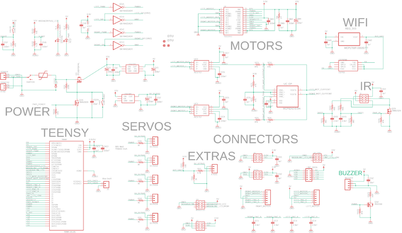
Figure 1. Schematic - click to get a readable version.
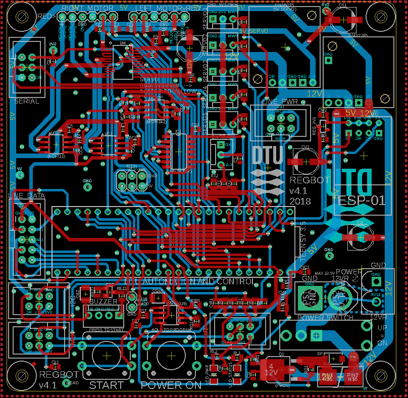
Figure 2. PCB layout
Figure 3. REGBOT main board with annotated connectors.
Figure 4. Version 4 board in place.


